2-10 Published 11-22-2016, Control # 345-12
HYDRAULIC SYSTEM RT9130E-2 SERVICE MANUAL
Section one also supplies the counterweight removal,
counterweight removal pin, boom removal pin, and cab tilt
functions, and when installed, the luffing jib function.
Section Two of Pump No. 1 supplies the front steer valve, the
swing/steer directional control valve, and if installed, the CE
option load sense steering valve. A load sense flow divider
located in the swing directional control valve ensures the
front steer valve gets priority flow upon demand and the
swing directional control valve gets any excess flow.
Pump No. 2
The torque converter drives Pump No. 2.
The hydraulic pump No. 2 priority port supplies the dual
accumulator charge valve and the hydraulic air conditioner.
The dual accumulator charge valve in the supply line
ensures the brake circuit gets priority flow and the hydraulic
air conditioner gets the excess flow.
The hydraulic pump No. 2 secondary port supplies the
charge air cooler fan.
Pump No. 3
The torque converter drives Pump No. 3.
Section one of pump No. 3 supplies the hoist, lift, and
telescope functions. It also supplies the rear axle oscillation
lockout valve.
Section two of pump No. 3 supplies the integrated outrigger/
rear steer valve and the pressure reducing sequence valve.
When the enabled solenoid is de-energized, the flow is
supplied to the “power beyond” port of the integrated
outrigger/rear steer valve which then is directed to the
pressure reducing sequence valve. When the enabled
solenoid is energized, the “power beyond” port is blocked
and the flow is only available to the integrated outrigger/rear
steer valve.
Pump No. 4
The engine drives Pump No. 4.
Pump No. 4 priority port supplies flow to the oil cooler motor
to drive it. Pump No. 4 secondary port returns oil to the
reservoir when the outrigger boost solenoid is de-energized.
When the outrigger boost solenoid is energized, the pump
supplies oil flow to the integrated outrigger/rear steer valve’s
outrigger valve.
MAINTENANCE
Troubleshooting
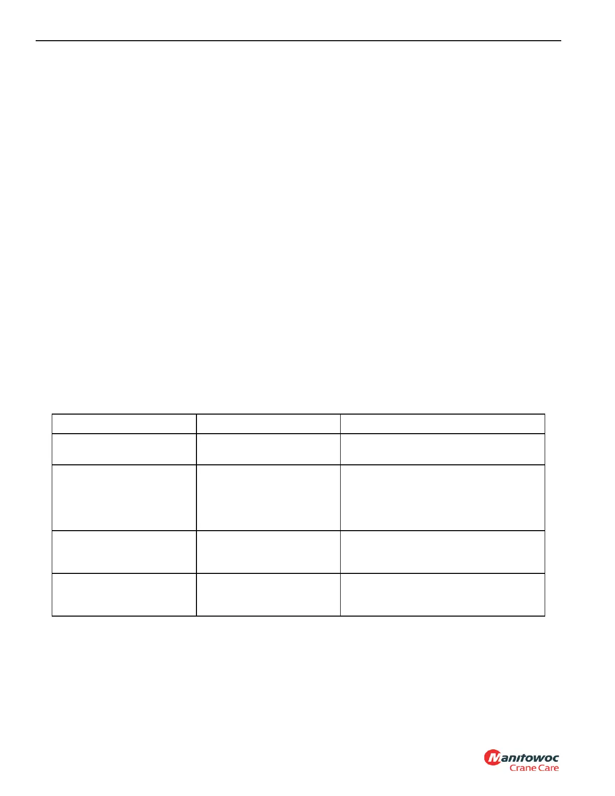
Table 2-2
Symptom Probable Cause Solution
1. No hydraulic oil flows in
systems.
a. Low hydraulic oil level. a. Check system for leaks. Make repairs
as needed. Fill reservoir.
b. Reservoir-to-pump
suction lines broken or
restricted. Air entering
at suction lines. Pump
not priming.
b. Clean, repair, or replace lines as
necessary. Check lines for security,
absence of cracks, and proper
attachment. Tighten, repair, or
replace parts as necessary.
c. Pump shaft sheared or
disengaged.
c. If drive shaft is damaged or sheared,
remove and repair or replace as
necessary
d. Internal
contamination.
d. Drain, flush with recommended oil
mixture, then drain and refill system
with recommended hydraulic oil.
 Loading...


