Grove Published 11-22-2016, Control # 345-12 2-43
RT9130E-2 SERVICE MANUAL HYDRAULIC SYSTEM
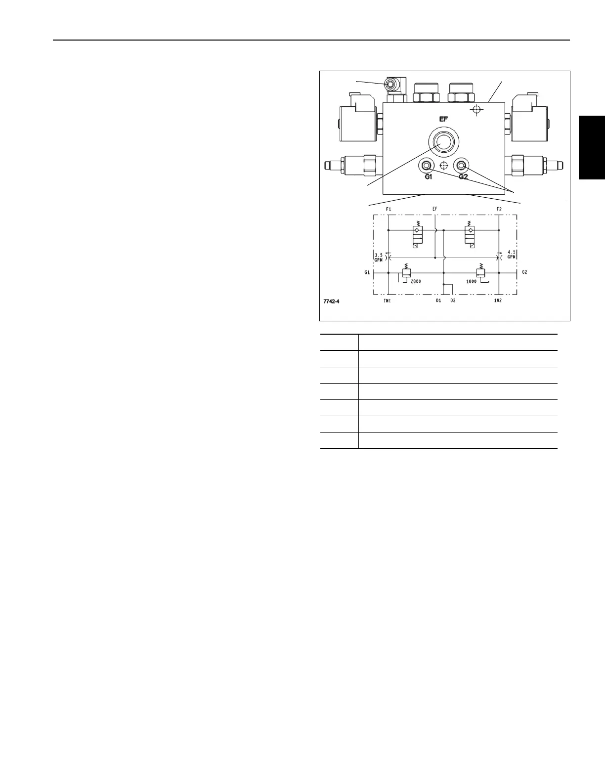
DUAL MOTOR CONTROL VALVE
Description
The dual motor control valve Figure 2-24 controls hydraulic
flow to the hydraulic oil cooler fan and the cold air charge
(CAC) fan. It is located inside the frame behind the right side
of the turntable in front of the axle disconnect and park valve.
One work port is connected to the hydraulically operated oil
cooler fan motor. The other work port is connected to the
hydraulically operated CAC fan motor. The solenoid valves
open to allow oil flow to each circuit when the engine is
running. Each circuit has a relief valve to limit pressure and
an orifice to limit oil flow. The valve also has two test fittings
to aid in setting the pressure of the relief valves.
Maintenance
Removal
1. Tag and disconnect the hydraulic lines to the valve.
2. Tag and disconnect the electrical connectors to the
valve.
3. Remove the bolts and washers securing the valve and
remove the valve.
Installation
1. Install the valve and secure in place with the bolts and
washers.
2. Connect the electrical connectors to the valve.
3. Connect the hydraulic lines to the valve.
Item Description
1 Pressure Port from Pump 4
2 Tank Port
3 Pressure Port from Pump 2
4 Oil Cooler Fan Port
5 CAC Fan Port
6 Test Fittings

 Loading...


