2-52 Published 11-22-2016, Control # 345-12
HYDRAULIC SYSTEM RT9130E-2 SERVICE MANUAL
4. From the access holes in the opposite side of the boom,
relieve the pressure in the lower telescope cylinder by
loosening the bleed plug.
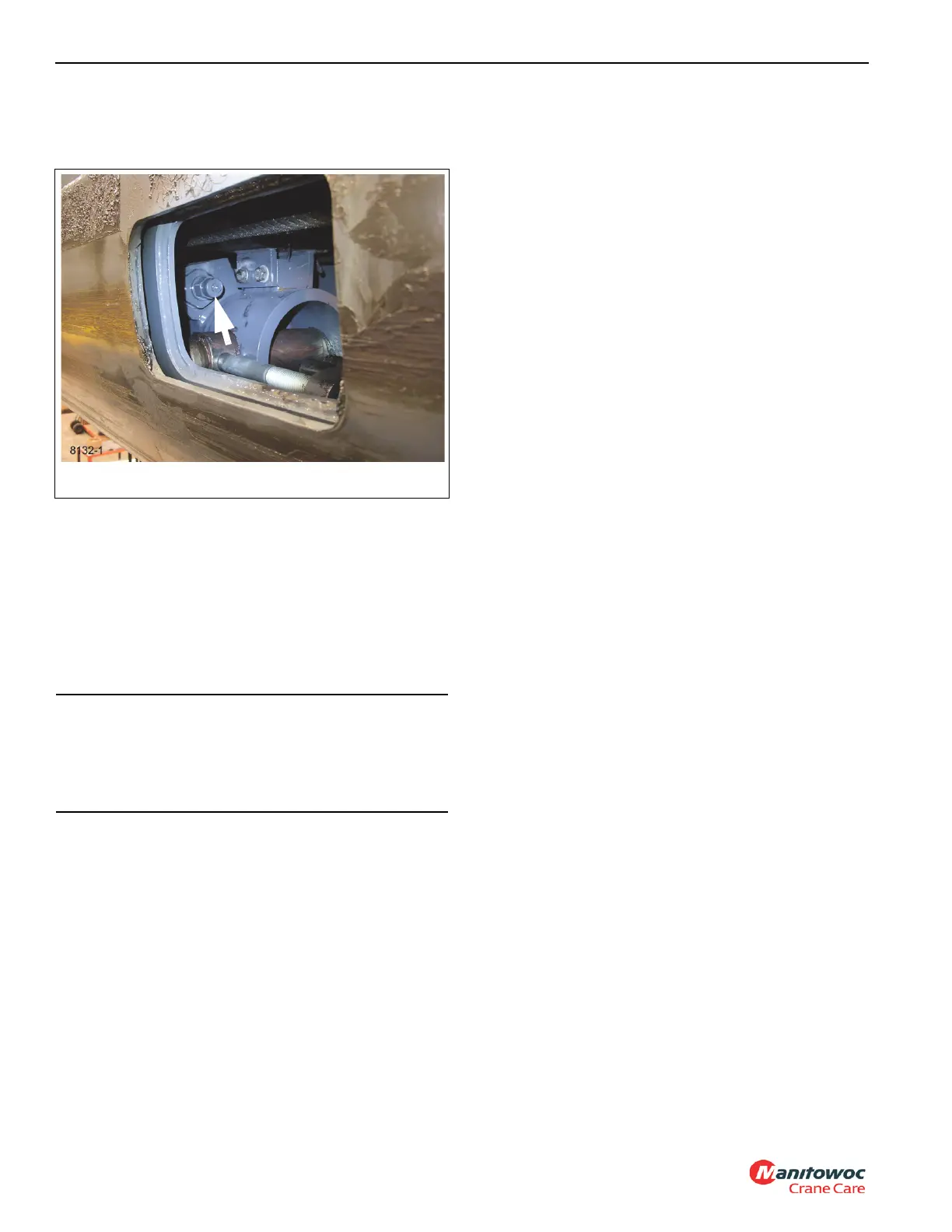
5. Unscrew holding valve from its port block. (See
Figure 2-31.)
Installation
1. Check the inside of the port block for any sharp edges or
burrs and remove as necessary with emery cloth.
2. Install new O-rings onto the holding valve.
3. Lubricate the holding valve and O-rings with clean
hydraulic oil.
NOTE: The holding valve should turn by hand until
compression of the O-rings begins.
4. Carefully install the holding valve into the port block until
fully seated.
5. Remove the telescope hold valve tool.
6. Test the check valve and port block by operating the
telescope cylinder. Verify telescope cylinder works
without problems; verify there is no leaking. Make
repairs as needed.
SHUTTLE VALVE
Description
The in-lined plumbed shuttle valve is used as a directional
selector valve. It is located at the inlet of the telescope rod
drain solenoid valve. It is used to direct the higher trapped
pressure of the rod side telescope cylinders to the telescope
rod drain solenoid valve inlet.
It consists of a ball that moves between two opposing check
seats. When one port is pressurized, the ball is forced
against the opposite seat, blocking that inlet and providing a
flow path to the outlet port.
Maintenance
Removal
1. Tag and disconnect hydraulic lines from valve and cap or
plug all openings, and remove valve.
Installation
1. Connect the hydraulic lines as tagged during removal.
2. Check valve and hydraulic connections for leaks. Make
repairs as needed.
CAUTION
Do not damage the O-rings during installation of the
holding valve. If the holding valve turns freely then gets
hard to turn, then easy to turn; remove the holding valve
and check the O-rings. They have probably been
damaged by a sharp edge of a port.

 Loading...


