BOOM RT9130E-2 SERVICE MANUAL
4-8 Published 11-22-2016, Control # 345-12
11. Block the lift cylinder.
12. Remove the capscrew and washer securing the upper
lift cylinder shaft to the side of the attach fitting on the
boom.
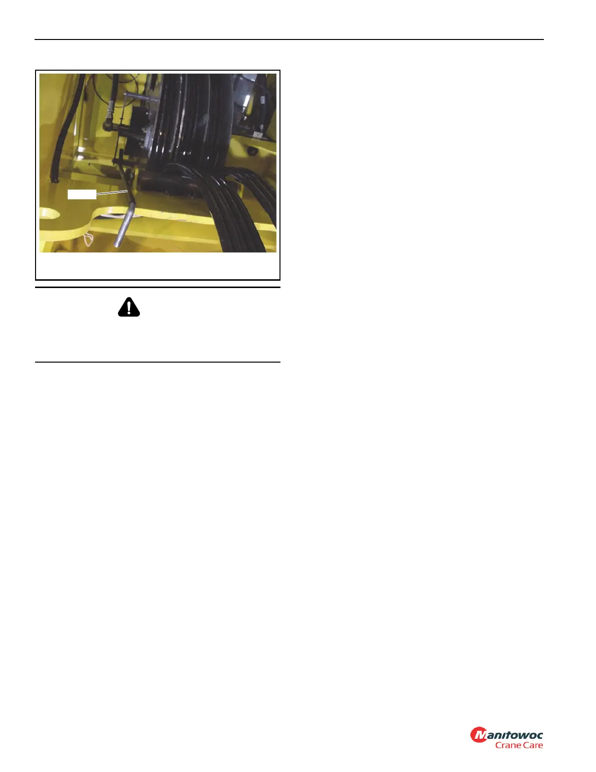
13. Insert the pump lever (found in cab) into the hand pump
located on the left side of the boom. Turn the pump flow
control lever clockwise and pump the lever until the
upper lift cylinder pin is clear of the boom’s left side lift
cylinder attachment lug. The lift cylinder may need to be
raised or lowered to aid in the release of the lift cylinder
pivot shaft from the attachment lug. This can be done by
using the jack on the lift cylinder support.
14. Once the shaft is clear of the attachment lug, activate the
hydraulic system and retract the lift cylinder enough to
clear the attachment lugs. For removal of the lift cylinder
from the crane refer to the removal procedures outlined
in Lift Circuit, page 4-32 in this section.
15. Take up the slack on the boom lifting device.
16. Remove the capscrews and lockwashers from the two
pivot lock weldments that retain the pivot shafts to the
boom and the turntable weldment. Remove the hoses
from the counterweight removal cylinder, and match up
the quick disconnects of the hoses to the disconnects on
the pivot shaft removal cylinder. Activate the cylinder to
pull the pivot shafts inward, to clear the bushings in the
turntable weldment and in the boom.
17. Raise the boom clear of the crane and lower to ground
and set cribbing to support the boom and prevent
tipping.
Boom Disassembly
NOTE: Boom assembly illustration shown in (Figure 4-5)
1. Remove the boom in accordance with the Removal
procedures outlined in this section.
2. If necessary, on the left side of the boom remove the two
bolts and washers securing the RCL cable angle
brackets to the base, inner mid, center mid, and outer
mid.
NOTE: The boom weighs approximately 34,000 lb (15420
kg). The above weight is for the boom without the
swingaway boom extension attached.
The boom assembly must be rotated 180° (upside
down) before performing any assembly or
disassembly procedures.
A rollover fixture with webbing is recommended to
rotate boom and sections. Chains are not
recommended. If a rollover fixture is not available,
rotate sections using adequate support with
webbing.
A secure fixture that will prevent damage to the
boom is recommended to stabilize and hold the
boom from moving during removal of section or
sections.
3. On the top front of the base section, remove the
capscrews, washers, nuts and three cable pads.
4. Repeat step 3 on the inner mid, removing three cable
pads.
5. Repeat step 3 on the center mid, removing two cable
pads.
6. Repeat step 3 on outer mid, removing two cable pads.
DANGER
Crushing Hazard!
Ensure the boom lift cylinder is properly supported before
disconnecting it from the boom.
 Loading...


