2-62 Published 11-22-2016, Control # 345-12
HYDRAULIC SYSTEM RT9130E-2 SERVICE MANUAL
TELESCOPE CYLINDER CHARGE VALVE
MANIFOLD (IF EQUIPPED)
Description
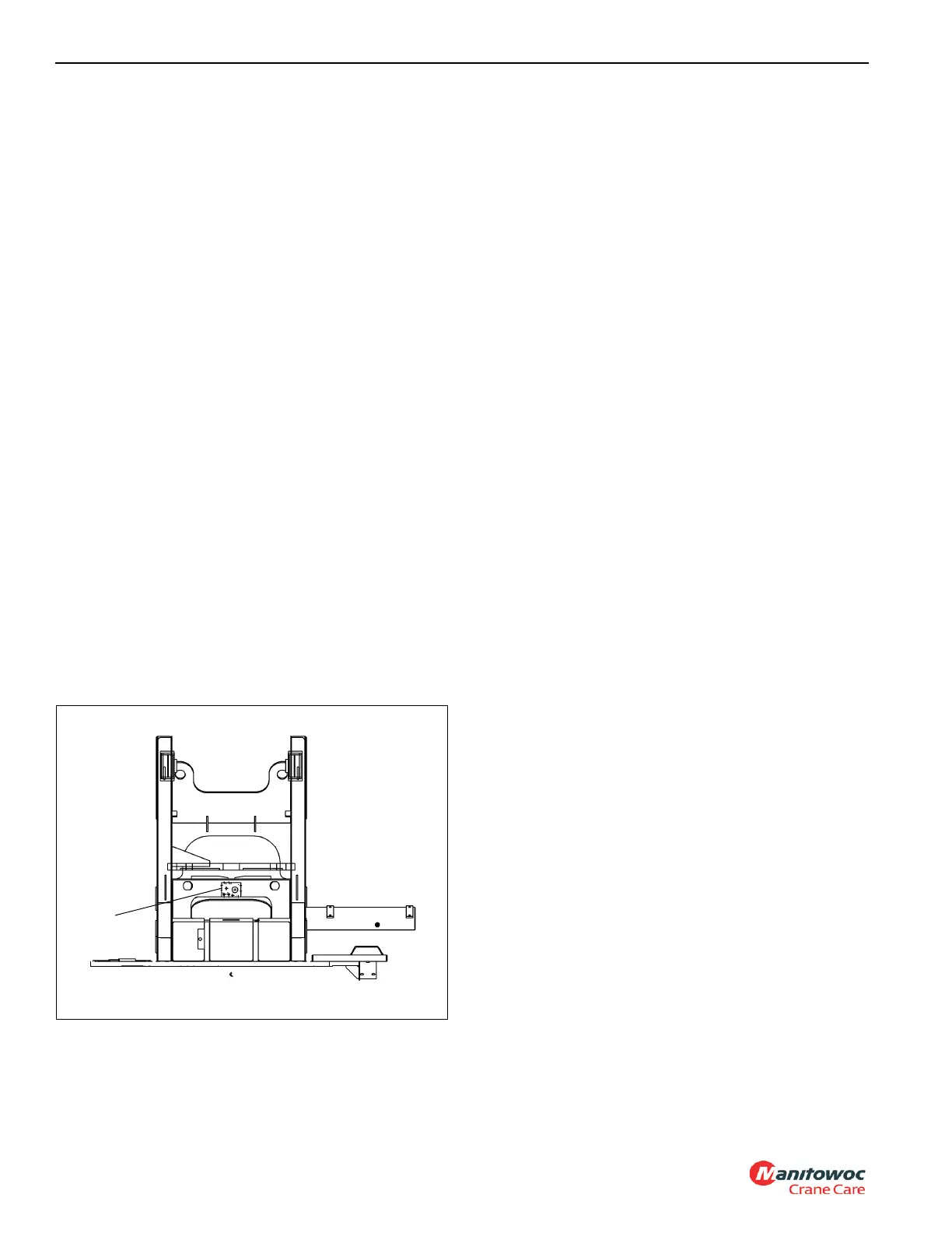
The telescope cylinder charge valve manifold is used in the
telescope cylinder charge system. The charge valve
manifold is mounted to the stiffener bracket, which is located
behind the swivel, that connects the two vertical sections of
the turret together (1, Figure 2-36).
The charge valve manifold (Figure 2-37) consists of a
manifold (1); a spring offset, solenoid controlled, two-way
control valve with integral check valve (2); a pressure
reducing valve (3) set to 13.8 bar (200 psi); two check valves
(4); and a normally-closed pressure switch (5).
The telescope cylinder charge valve manifold prevents the
boom from retracting due to thermal contraction of the oil in
the telescope cylinders under certain circumstances (refer to
Telescope Circuit, page 4-24 for more detailed information).
The charge valve manifold does this by supplying oil to the
telescope cylinder extend circuits when the boom is elevated
above 35 degrees. The solenoid valve (2) is energized by the
LMI when the boom angle is greater than 35 degrees,
allowing oil to flow through the pressure reducing valve (3)
and on to the telescope extend circuits. Pressure in the
telescope extend circuits is maintained by the two check
valves (4). The normally-closed pressure switch (5) is
plumbed into the charge valve manifold and is used to alert
the operator by way of a buzzer and warning indicator if the
pressure in the telescope cylinder charge system is less than
approximately 6.9 bar (100 psi). For a schematic of the
telescope cylinder charge system, refer to Figure 2-38.
Checking/Setting the Charge Valve Manifold
1. Install pressure check diagnostic quick disconnect
(Parker PD240) with gauge onto test nipple @ GPA or
GPB on the charge valve manifold.
2. Boom lift up to achieve a boom angle greater than 35°
(Boom Telescope cylinder must be fully retracted).
3. With the engine at idle rpm, check to ensure pressure is
200 psi. If the pressure is low, adjust the pressure
reducing valve (3, Figure 2-37) adjusting stem clockwise
(in). If pressure is higher than specification, adjust the
adjustment stem Counter Clockwise (out).
4. Once pressure is set move pressure transducer to the
other (GPA or GPB) diagnostic coupler on the make-up
oil manifold check to ensure the pressure reads the
same as set in step #3.
5.
Stop engine and remove transducer
Maintenance
Removal
1. Tag and disconnect the electrical connectors to the
valve.
2. Tag and disconnect the hydraulic hoses from the valve.
Cap or plug the lines and ports.
3. Remove the capscrews, nuts and washers securing the
valve to the turret bracket. Remove the valve.
Installation
1. Secure the valve to the crane with the capscrews, nuts
and washers.
2. Connect the hydraulic hoses to the ports on the valve as
tagged during removal.
3. Connect the electrical connectors to the valve as tagged
during removal.
4. Elevate boom above 35 degrees and ensure buzzer
does not sound and telescope cylinder charge indicator
does not illuminate.
5. Check valve and hoses for leaks. Make repairs as
needed.

 Loading...


