BOOM RT9130E-2 SERVICE MANUAL
4-2 Published 11-22-2016, Control # 345-12
Boom Control Switches
The following switches and indicators are located in the
crane’s superstructure cab and are used together to control
the boom telescope function.
Boom Auto/Manual Telescope Mode
Switches
The boom auto/manual telescope mode switch and indicator
are located on the overhead control panel. The switch is a
two-position rocker switch.
When the switch is in the Auto mode, the boom sections
extend in a predetermined sequence when telescoping the
boom; the inner mid extends 75% and stops, then the center
mid extends to 75% and stops, then the inner mid extends to
100%, the center mid extends to 100%, and then the outer
mid and fly section extend in a synchronized fashion. The
sections retract in the same manner in reverse order.
When in the manual mode, the switch will illuminate. The
boom telescope section select switch is positioned to either
the center mid or inner mid position in order to extend or
retract the selected section until it is returned to the proper
position for normal boom synchronization to occur.
Center Mid/Inner Mid Boom Telescope
Sections Select Switch
The center mid/inner mid boom telescope section select
switch is located on the overhead control panel. This switch
is a three position rocker switch that is used in conjunction
with the boom auto/manual telescope mode switch. When
the boom mode switch is positioned to manual, the boom
telescope section select switch is positioned to either of the
two positions. When placed in the upper position, the center
mid can be extended. When the center mid is fully extended,
the outer mid and fly can be controlled. The switch will
illuminate when the it is positioned in either the inner mid or
center mid position.
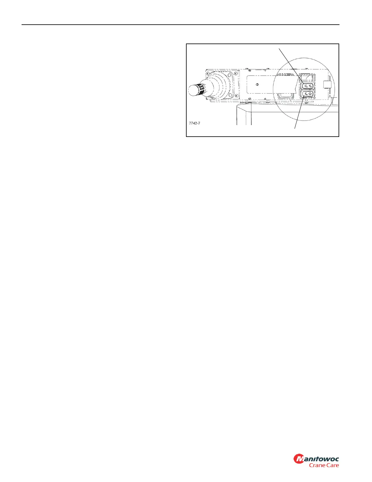
Luffing Jib Switches
The luffing jib switches are located on the right armrest. Each
switch is two position. The power switch (1) (Figure 4-1)
enables the RAISE/LOWER momentary switch (2) that
energizes a solenoid to raise or lower the jib, when in the ON
position.
THEORY OF OPERATION
Boom Extension
Boom extension and retraction is accomplished with two
telescope cylinders, five extension cables, and two retraction
cables. The lower telescope cylinder is a two stage cylinder.
The rod for the first stage is secured to the rear of the boom
base section and the barrel of the first stage is secured to the
inner mid boom section by a trunnion. The second stage of
the first telescope cylinder barrel is secured to the rear of the
center mid boom section by a trunnion. The rod end of the
upper telescope cylinder is attached to the rear of the center
mid and the barrel is secured to the outer mid boom section
by a trunnion. The extension cables are secured to the back
of the fly section and run around extension sheaves on the
front of the upper telescope cylinder to the front of the
second stage barrel of the lower telescope cylinder.
The hydraulic fluid for the first stage of the lower cylinder is
supplied by hoses from the turntable. The hydraulic fluid for
the second stage of the lower cylinder and the upper cylinder
is routed through the hose reel that is mounted in the
turntable into a manifold that is attached at the rear of the
center mid section. There are two cam operated check
valves mounted at the rear of the center mid which control
flow to the second stage of the lower cylinder and the upper
telescope cylinder. With both cylinders retracted, the check
valve for the second stage of the lower telescope cylinder is
open and the check valve for the upper cylinder is closed
allowing the second stage of the lower cylinder to extend.
When the lower cylinder is fully extended, the check valve for
the upper cylinder opens allowing the upper cylinder to
extend. The check valve for the lower cylinder closes after
the upper cylinder starts to extend and shuts off the flow to
the lower cylinder. As the upper telescope cylinder barrel
extends, the extend cables around the extend sheaves on
the end of the cylinder barrel push on the extend cables to
pull the fly section out at the same time the outer mid is
extending.

 Loading...


