Grove Published 11-22-2016, Control # 345-12 2-29
RT9130E-2 SERVICE MANUAL HYDRAULIC SYSTEM
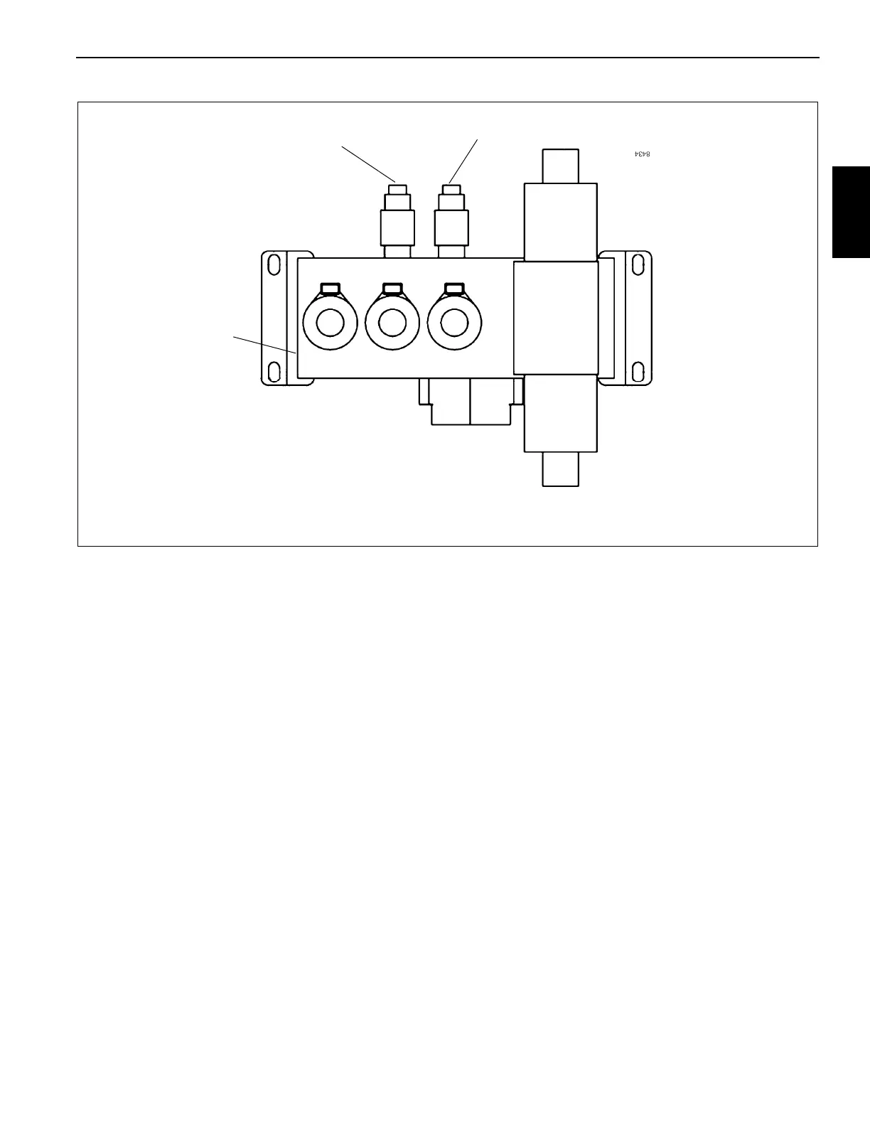
Procedure K - For Checking Outrigger/Rear
Steer Relief Valve Pressure
1. Remove cap and install pressure gauge (Figure 2-14)
on outrigger/rear steer valve pressure check port.
2. With engine running at full RPM, fully extend one
outrigger beam. Adjust the sequence relief valve to
2000 psi
±50 (13.8 MPa ±0.4). If adjustment is required,
remove socket head plug from end of cartridge. Adjust
internal socket head plug in (CW) to increase pressure
or out (CCW) to decrease pressure. When complete,
reinstall socket head plug into end of cartridge.
3. With the engine running at full RPM, fully extend one
outrigger jack cylinder. Adjust the outrigger jack/ rear
steer/ pin removal relief valve to 3500 psi
±50 (24.2 MPa
±0.4). If adjustment is required, loosen locknut and use
1/4 inch Allen wrench to turn adjustment screw in (CW)
to increase pressure or out (CCW) to decrease
pressure. When complete, tighten locknut.
4. Remove pressure gauge from outrigger/rear steer valve
and reinstall cap.
Procedure L - For Checking/Setting the
Make-up Oil Manifold (Thermal Contraction)
1. Install pressure check diagnostic quick disconnect
(Parker PD240) with gauge onto test nipple @ GPA or
GPB on the make-up oil manifold (Figure 2-15).
2. Boom lift up to achieve a boom angle greater than 35°
(Boom Telescope cylinder must be fully retracted).
3. With the engine at idle RPM, check to ensure pressure is
200 psi. If the pressure is low, adjust the pressure
reducing valve adjusting stem clockwise (in). If pressure
is higher than specification, adjust the adjustment stem
counterclockwise (out).
4. Once pressure is set move pressure gauge to the other
(GPA or GPB) diagnostic coupler on the make-up oil
manifold check to ensure the pressure reads the same
as set in step #3.
5. Stop engine and remove quick disconnect.
FIGURE 2-14
Pressure Check Port
Outrigger Beam Extend Relief
Outrigger/Rear Steer Valve
Outrigger Jack/Rear Steer/Pin
Removal Relief

 Loading...


