3-4 Published 11-22-2016, Control # 345-12
ELECTRICAL SYSTEM RT9130E-2 SERVICE MANUAL
The fuse and relay panel (Figure 3-3) contains 2 relays ACC
#1 and ACC #2 (K1 and K2), the cab fuse panel, and a
buzzer. It is located behind the driver’s seat in the cab.
Access is gained by removing the cover thumb screws.
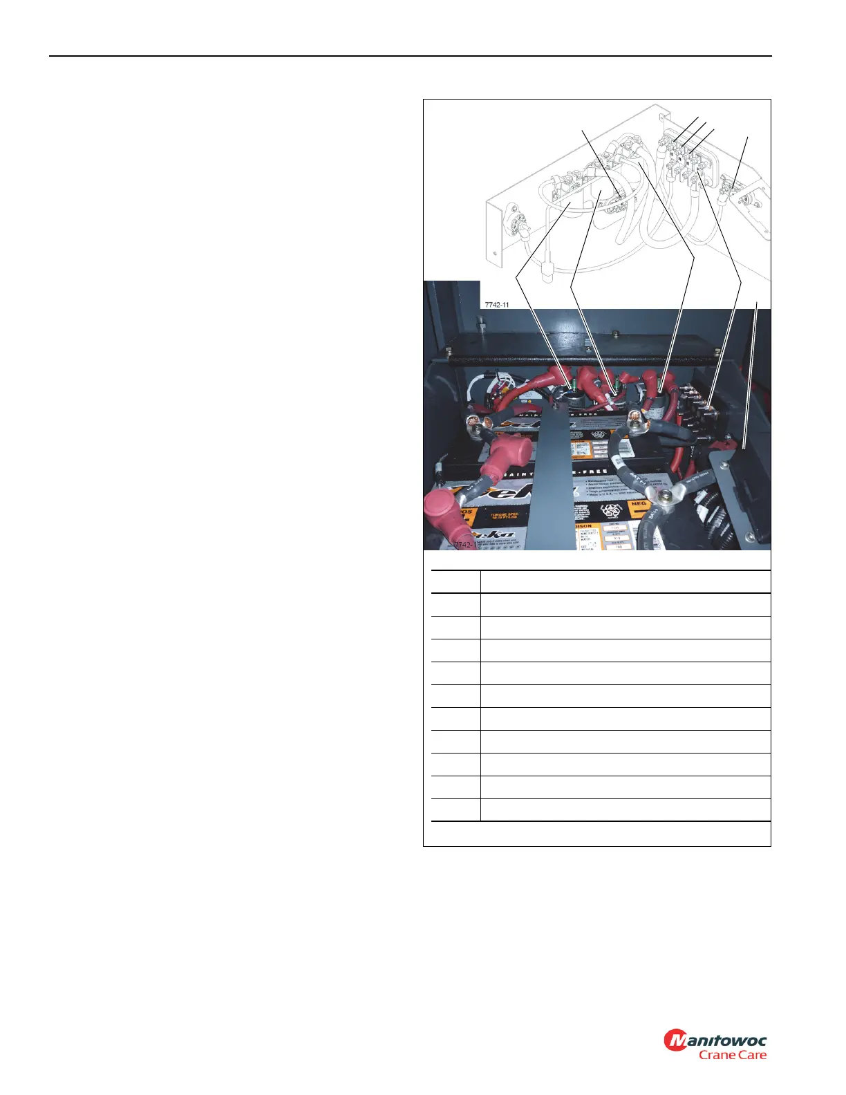
The crane has 5 or 6 relays which control many of its
functions. In addition to relays K1 and K2 in the cab, relays
K301, K302, and K303 are located in the battery box
(Figure 3-5).
The coil of the start relay (K303) is energized when the
transmission is in neutral and the ignition switch is at the
START (2) position.
The coil of the accessory relays (K1 and K2) are energized
when the ignition switch is at the RUN (1) or ACC (3)
position.
For cranes with air conditioning, there is an optional AC Fans
relay (A/C).
4
5
6
7
8
9
1
2
3
Item Description
1 Power Relay (K301)
2 Start Relay (K303)
3 Grid Heater Relay (K302)
4 250 Amp Fuse (F53)
5 100 Amp Fuse (F54)
6 100 Amp Fuse (F55)
7 100 Amp Fuse (F56)
8 100 Amp Fuse (F52)
9 250 Amp Fuse (F51)
10 Fuse and Relay Panel (see Figure 3-6)
FIGURE 3-5
10
 Loading...


