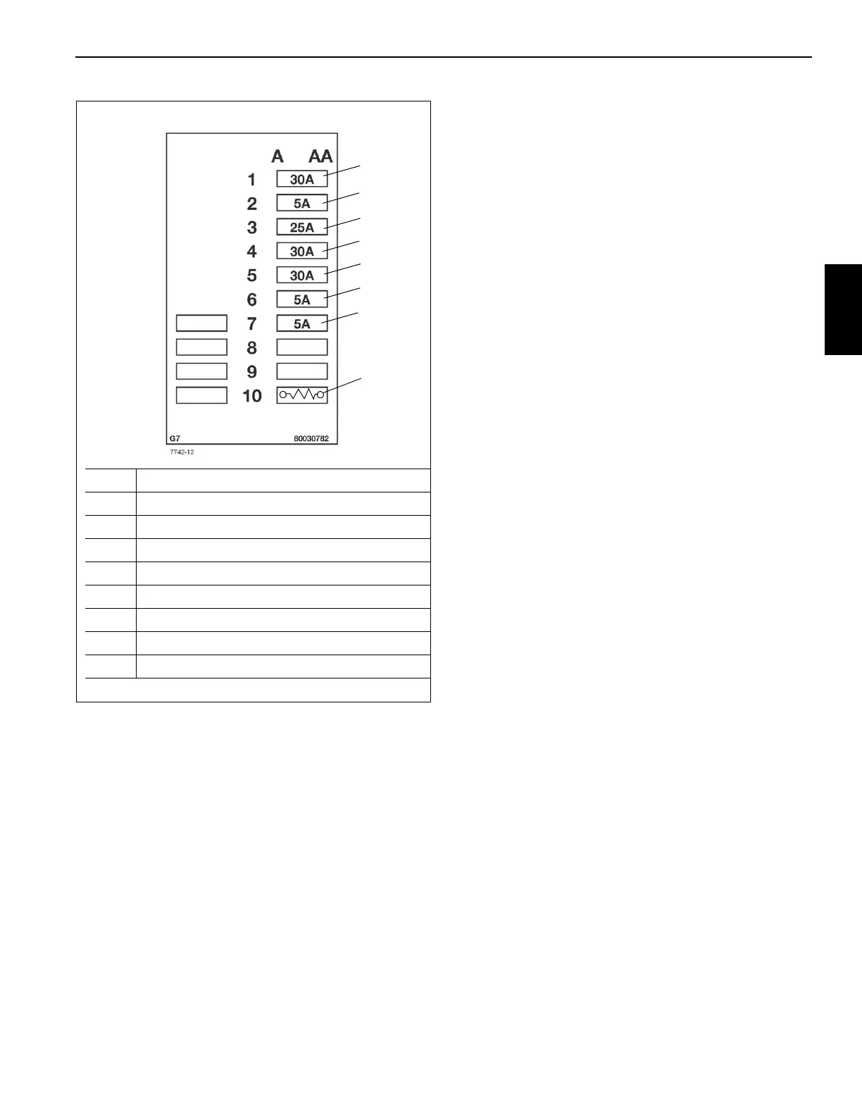
EasyManua.ls Logo

Manitowoc Grove RT9130E-2 - Page 145

Manitowoc Grove RT9130E-2
360 pages
Print Icon
To Next Page IconTo Next Page
To Previous Page IconTo Previous Page
Loading...
Grove Published 11-22-2016, Control # 345-12 3-5
RT9130E-2 SERVICE MANUAL ELECTRICAL SYSTEM
3
For the grid heater relay coils to energize, the battery must
be connected and signals from the engine ECM must be
sent.
FIGURE 3-6
5
6
7
10
4
3
2
1
Item Description
1 ECM, 30 Amp Fuse (F1)
2 Swivel, 5 Amp Fuse (F2)
3 Carrier, Center Module, 25 Amp Fuse (F3)
4 Carrier, Center Module, 30 Amp Fuse (F4)
5 Carrier, Front Module, 30 Amp Fuse (F5)
6 Diagnostic Connector, 5 Amp Fuse (F6)
7 Power Control Relay, 5 Amp Fuse (F7)
10 120 Ohm Resistor, Starter Lockout Circuit

Table of Contents

Other manuals for Manitowoc Grove RT9130E-2

Related product manuals