Grove Published 11-22-2016, Control # 345-12 8-21
RT9130E-2 SERVICE MANUAL UNDERCARRIAGE
Maintenance
Removal
1. Chock the wheels to prevent crane movement.
2. Start the engine, ensure the transmission is in neutral,
and position the Park Brake Switch to OFF. This will
pressurize the brake actuator to release the tension on
the brake linkage. Air pressure of 170 to 270 psi (1172 to
1862 kPa) may be used to pressurize the actuator.
Screw the caging nut up under the actuator chamber.
3. Position the Park Brake Switch to ON and shut down the
engine.
4. Tag and disconnect the hydraulic hose from the actuator.
Cap or plug all openings.
5. Unthread the two mounting bolts securing the brake
assembly to the mounting bracket, then carefully
remove the brake assembly from the mounting bracket
and the brake disc.
6. Repeat steps 4 and 5 for the second caliper.
Installation
1. Slide the brake over the disc and align with mounting
bracket holes.
NOTE: Mount the brake so that the linings are parallel with
the disc within 0.015 in.
2. Start the hex mounting bolts into the mounting bracket
far enough to just support the brake.
3. Remove plug, loosen the coupling nut and tighten
socket setscrew until linings are clamped to the disc.
This locates and holds the brake in the proper position to
set the hex mounting bolts and hex nuts.
4. Tighten hex mounting bolts until they make contact with
the urethane springs, then tighten 4 flats (approximately
0.07 in) more. This puts the proper amount of pre-load
on the urethane springs.
5. Tighten jam nut/sleeves against mounting surface.
6. Attach brake line to inlet port located on the top of the
hydraulic cylinder.
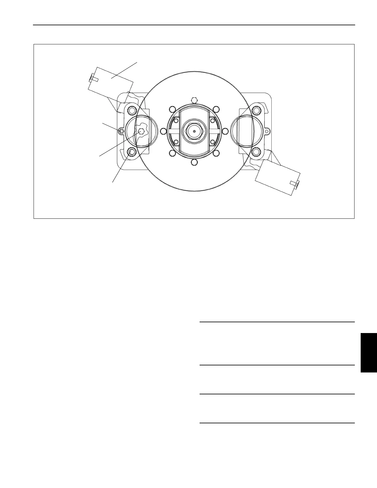
FIGURE 8-19
Carrier Retaining Bolt
Adjusting Bolt
Mounting Bolt
Park Brake Assembly
CAUTION
Brake linings are susceptible to contamination. When
installing or servicing brakes, keep all oil and fluids away
from the linings. Poor brake performance may result if
linings are contaminated.
CAUTION
To avoid damage to the brake, do not exceed 270 psi
(1861kPa) hydraulic pressure.
 Loading...


