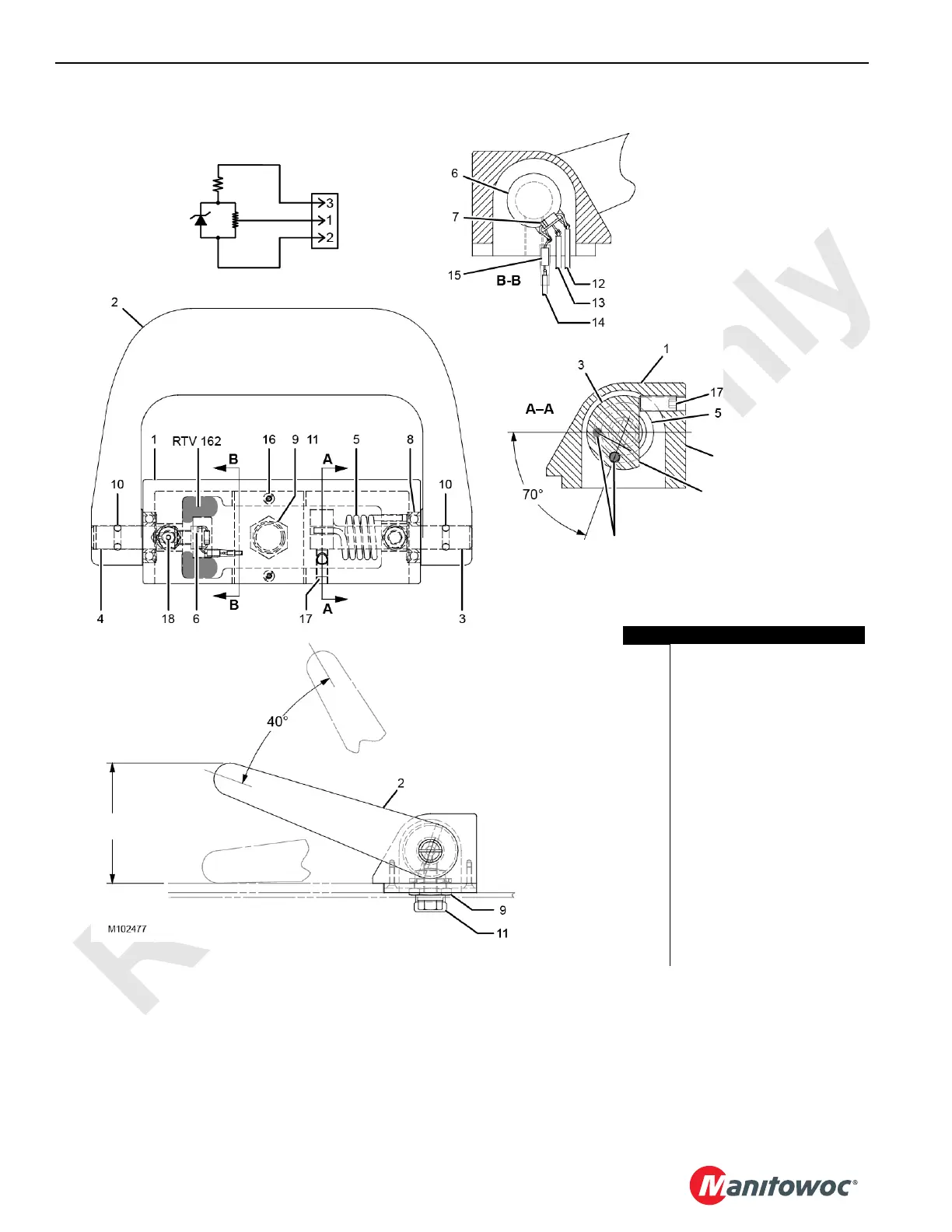
Item Description
1 Foot Pedal Housing
2 Foot Pedal
3 Foot Pedal Shaft (right)
4 Foot Pedal Shaft (left)
5 Torsion Spring
6 Potentiometer
7 Zener Diode
8 Roller Bearing (qty 2)
9 Conduit Nut
10 Roll Pin (qty 2)
11 Receptacle/Control Wires
12 Black Wire (ground)
13 Green Wire (signal)
14 White Wire (supply)
15 Resistor
16 Flat Head Brass Screw (qty 2)
17 Setscrew, 3/4 in
18 Setscrew, 3/16 in
Potentiometer (Elect. Schematic)
Supply (white)
Signal (green)
Ground (black)
:Low Idle
High Idle
Surface X
These two holes should be
aligned when initially inserting the
shaft and spring into the housing.
Pedal Position A
:
Low Idle
High Idle
Pedal Position B
83 mm (3-1/4 in)
89 mm (3-1/2 in)
Flat on the Head
of the Shaft
FIGURE 7-17
 Loading...


