Manitowoc Published 11-20-19, Control # 234-19 1-1
MLC300 OPERATOR MANUAL INTRODUCTION
SECTION 1
INTRODUCTION
CRANE DATA
See the end of this section for crane data specific to your
crane:
• Basic Specifications
• EC Declaration (if applicable)
CRANE WEIGHTS
See the end of this section for crane weights.
OUTLINE DIMENSIONS
See the end of this section for outline dimensions.
CHANGE OF OWNERSHIP REGISTRATION
If you are the new owner of a Manitowoc crane, please
register it with Manitowoc Crane Care so we can contact you
if the need arises.
1. Go to www.manitowoccranes.com
.
2. Go to Parts & Service > Service Support > Change of
Ownership Form.
3. Complete the form.
MANITOWOC DEALER
For questions about this manual or the MLC300 crane,
contact your Manitowoc dealer. If you do not know the
contact information for your dealer, locate the Manitowoc
dealer nearest you, as follows:
1. Go to www.manitowoccranes.com
2. Go to Dealer Locator.
3. Follow the on-screen prompts to locate your Manitowoc
dealer.
CRANE/ATTACHMENT IDENTIFICATION
An identification plate is attached to the outside of the
operator cab (see Figure 1-1) and to the attachments (for
example, luffing jib and VPC-MAX).
The crane or attachment model and serial number are
provided on the plate.
For the exact location of the identification labels on your
crane and attachments, refer to the Nameplates and Decals
Drawing in Section 2 of this manual.
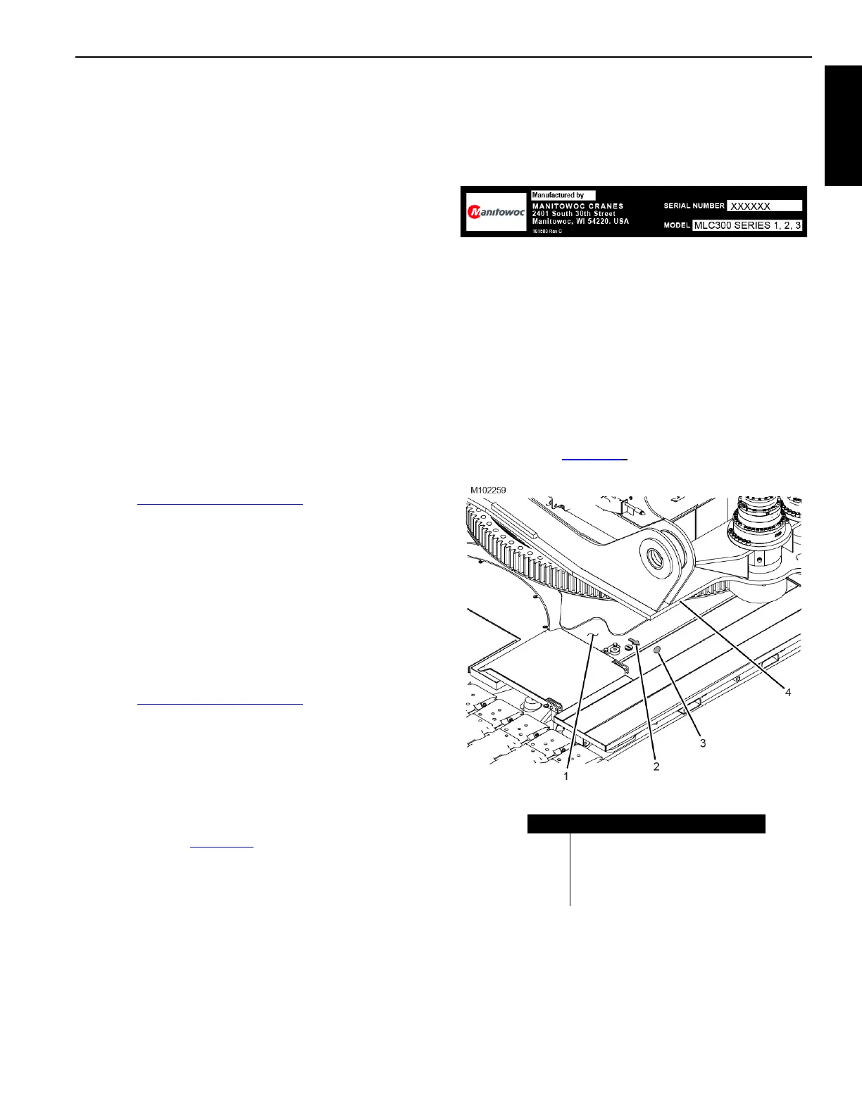
CRANE ORIENTATION
The terms RIGHT, LEFT, FRONT, REAR used in this
manual refer to operator’s right, left, front, and rear sides
when seated in the operator cab looking forward.
• The swing drives are on the front of the rotating bed.
• The operator cab is on the left side of the rotating bed.
• A yellow arrow (2) and dot (3) on the right top and right
front sides of the carbody indicate the FRONT of the
carbody (see Figure 1-2
).
Figure 1-1. Identification Plate
Figure 1-2. Carbody Orientation Arrow
Item Description
1 Carbody
2 Yellow Arrow on Front of Carbody
3 Yellow Dot on Front of Carbody
4 Front of Rotating Bed