Manitowoc Published 11-20-19, Control # 234-19 3-57
MLC300 OPERATOR MANUAL OPERATING CONTROLS AND PROCEDURES
RIGHT CAB WINDOW OPERATION
See Figure 3-8 for the following procedure.
Closing Window
Rotate the window latch handle DOWN to the position shown
in View A.
Opening Window For Ventilation
Rotate the window latch handle UP to the position shown in
View B. The window can be swung open approximately 76
mm (3 in) for ventilation.
OPERATOR CAB EMERGENCY EXIT
Using the life hammer provided, smash the front window to
exit the operator cab in an emergency. The hammer is stored
on the left wall inside the operator cab.
CAB DOOR ADJUSTMENT
Refer to F2297 at the end of this section for Vision Cab Door
Adjustment procedures (for example: door brake and door
damper).
CAB TILT STOP PINS INSTALLATION
The cab tilt stop pins (1, Figure 3-9) on the rear of the cab
support (3) must be in the working position for crane
operation. The cab will hit the crawlers and be damaged
when the crane is swung if the cab is tilted down below
horizontal.
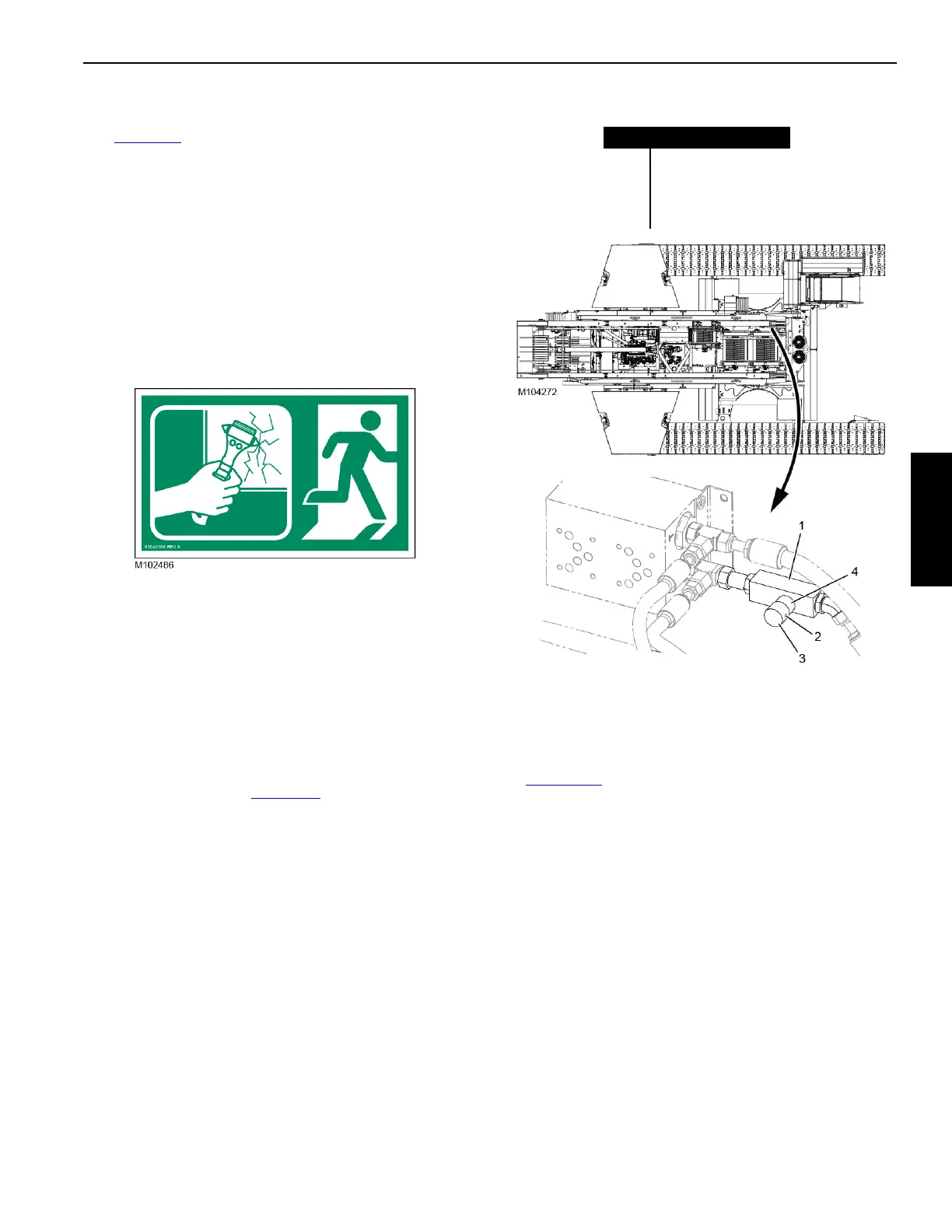
CAB TILT SPEED ADJUSTMENT
The cab tilt speed can be adjusted at the flow control valve
(1, Figure 3-10
). The valve is located on the left-front inside
wall of the rotating bed.
1. Loosen the set screw (2).
2. Turn the adjusting knob (3) fully clockwise (in) so that no
color bands (4) appear.
3. Adjust the flow control valve to the desired setting by
turning the adjusting knob (3) counterclockwise (out).
The recommended initial setting is to turn the adjusting
knob out until only the first green color band is showing.
4. Test the operation of the cab tilt using the switch in the
cab.
5. If necessary, turn the adjusting knob out or in to obtain
the desired speed.
6. Securely tighten the set screw (2).
Figure 3-10. Cab Tilt Flow Control Valve
Item Description
1 Flow Control Valve
2 Set Screw
3 Adjusting Knob
4 Color Bands