Manitowoc Published 11-20-19, Control # 234-19 4-23
MLC300 OPERATOR MANUAL SETUP AND INSTALLATION
Install Rotating Bed Handrails
See Figure 4-19 for the following procedure.
The rotating bed has eleven handrails. The heaviest handrail
weighs 9 kg (20 lb).
Use a tagline to lift each handrail into position.
For proper installation, match the identification number (10)
on the handrail with the identification number on the
platform.
1. Lift the desired handrail (1-7) into position with a tagline.
2. Align the legs of the handrail with the pockets in the
platform.
3. Align the connecting holes and install the safety pins (8).
4. Repeat the steps until all handrails (1-7) are installed.
Deploy Rotating Bed Left-Rear Platform
AFTER the live mast is raised:
1. Rotate the left-rear platform (9, Figure 4-19
) from the
stored position to the working position.
2. Extend the handrail (6, Figure 4-19
) from the stored
position and pin it in the working position.
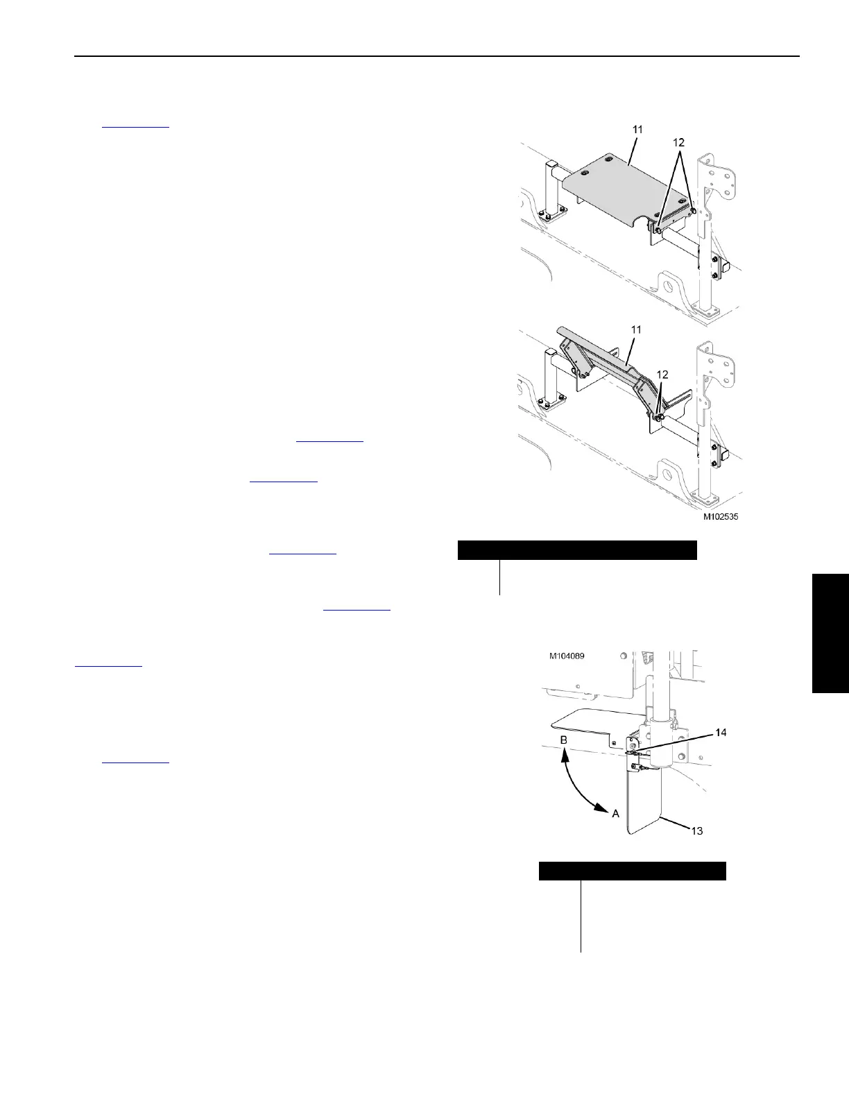
Deploy Valve Cover Platforms
Three valve cover platforms (11, Figure 4-19) are located in
the rotating bed.
For normal operation, always pin the two large platforms in
the operating position as shown in View A, Figure 4-20
.
For maintaining the hydraulic valves, pin the two large
platforms in the servicing position as shown in View B,
Figure 4-20
.
For maintaining the hydraulic valve under the small platform,
remove the platform. Reinstall it when done.
Deploy Exhaust Shield
See Figure 4-21 for the following procedure.
At the left rear ladder platform, proceed as follows:
1. Remove the quick-release pin (14).
2. Rotate the exhaust shield (13) to the proper position (A
or B).
3. Install the quick-release pin (14).
Figure 4-20
View A
OPERATING POSITION
View B
SERVICING POSITION
Item Description
11 Valve Cover Platform (3)
12 Quick-Release Pin (4 each platform)
Item Description
13 Exhaust Shield
14 Quick-Release Pin
A Down without VPC-MAX
B Up with VPC-MAX
Figure 4-21