OPERATING CONTROLS AND PROCEDURES MLC300 OPERATOR MANUAL
3-46
Published 11-20-19, Control # 234-19
OPERATING LIMITS IDENTIFICATION AND OPERATION
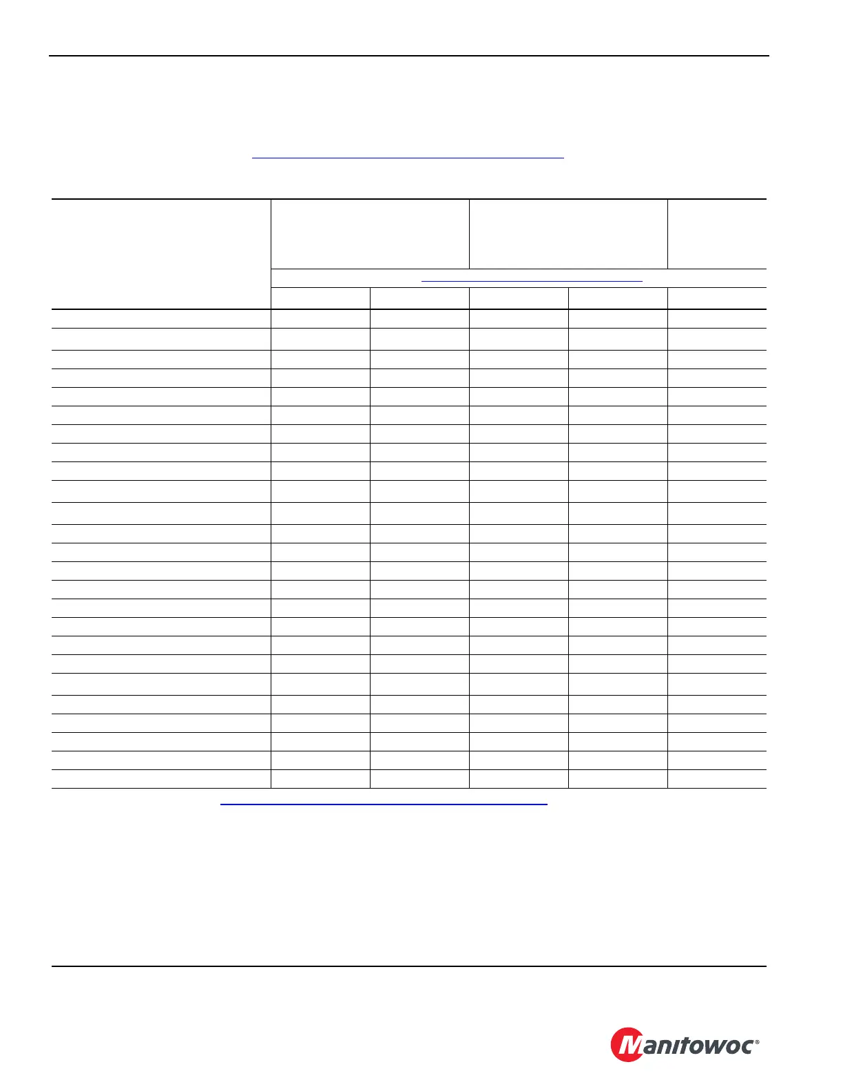
The following table lists the operating limits this crane is equipped with and identifies which of those limits are bypassable.
When a limit is reached, the operating limit fault is activated and the corresponding fault icon appears in the fault bar of the
Main Display Working Screen (see Table 3-17. Operating Limits Description on page 3-47
).
Table 3-16. Operating Limits Identification
Limit
Bypassable
Bypassable in Luffing Jib Setup
Mode On
1
Bypassable
with External
Override
Switch
2
See Limit Bypass Key Switch on page 3-17
Non-CE
3
CE
3
Non-CE
3
CE
3
CE
3
Bail, Minimum (each drum) No No No No No
Block Up (each drum) Yes
Yes
4
Yes Yes No
Boom Max Up NoNoNoNoNo
Function Diverted No No No No No
Function Parked No No No No No
Inactive Control Station (CE only) No No No No No
Luffing Jib Maximum Down 1 Yes No Yes Yes No
Luffing Jib Maximum Down 2 No No No No No
Luffing Jib Maximum Up 1 Yes No Yes Yes No
Luffing Jib Maximum Up 2
Yes
5
No
Yes
5
Yes
5
No
Luffing Jib Stop Latch
Yes Yes Yes
5
Yes
5
No
Mast (live) Accessory Fault No No No No No
Mast Arms Down Yes Yes No No No
Mast Arms Up Yes Yes No No No
Mast Too Far Back Yes Yes No No No
Mast Too Far Forward Yes Yes No No No
Mast (fixed) Stop NoNoNoNoNo
Operator Out of Seat No No No No No
Pawl Engaged No No No No No
Rated Capacity Indicator/Limiter Yes
Yes
4
Yes
Yes
4
Yes
6
Transducer Fault No No No No No
Travel on Grade with VPC Unlocked No No No No No
VPC Setup Prohibited No No No No No
VPC Setup Required No No No No No
VPC Sensor No No No No No
1
Use only for rigging. See Bypassing Limits in Luffing Jib Setup Mode on page 3-52.
2
Cranes meeting European requirements (CE) are equipped with an RCI/RCL External Override Switch located outside
the operator cab. See MLC300 Rated Capacity Indicator/Limiter Operation Manual.
3
CE = Cranes that comply with 2010 European requirements.
4
Only if boom or luffing jib is below allowable angle given in capacity chart (while raising or lowering boom and luffing jib
from or to ground level).
5
Only when boom is below 50°.
6
The speed of the crane functions is limited to 15% of their maximum speed for movements that increase load.