Manitowoc Published 11-20-19, Control # 234-19 4-33
MLC300 OPERATOR MANUAL SETUP AND INSTALLATION
Install Live Mast Package
See Figure 4-26 for the following procedure.
1. Remove the keeper pins (2, Views B1 or B2 and E) from
the mast hinge pins (3, View B1 or B2) and the equalizer
hinge pins (4, View E).
2. Store the keeper pins (2, Views A1 or A2 and D).
3. Using the remote control, disengage the mast hinge pins
(3, View A1 or A2) and the equalizer hinge pins (4, View
D).
4. Remove pins (5, View C) from the boom hoist mounting
frame (6) and place the pins to the side.
5. Lift the live mast package into position over the
upperworks.
The live mast will hang approximately 6° out of level.
6. Lower the live mast package until the alignment lugs (7,
View A1 or A2) on the mast (1) engage the alignment
rings (8) on the rotating bed lugs (9).
7. Using the remote control, engage the mast hinge pins
(3, View B1 or B2) and install the locking pins (2).
8. Continue to lower the live mast package until:
a. The alignment pins (10, View C) in boom hoist
mounting frame (6) engage the alignment notches
(11) in the rotating bed frame (12).
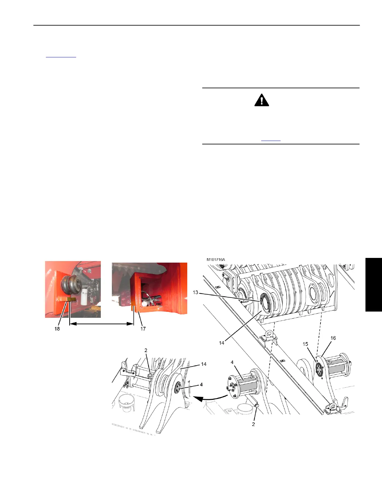
b. The alignment lugs (13, View D) on the boom hoist
equalizer (14) engage the alignment rings (15) on
the rotating bed lugs (16).
9. Using the remote control, engage the equalizer hinge
pins (4, View E) and install the locking pins (2).
10. To assist in accessing the pins (5, View C) in the next
step, you can extend the VPC trolley (17, View F)
rearward NO MORE THAN 813 mm (32 in) from the stop
blocks (18) on the rotating bed.
11. Install the pins (5, View C) to connect the boom hoist
mounting frame (6) to the rotating bed frame (12).
12. Disconnect the shackles and lifting slings from the live
mast.
Continued on next page.
WARNING
Tipping Hazard
To prevent the crane from tipping:
• Do not extend the VPC trolley rearward any more
than specified in step 10
.
Figure 4-26 continued
View D
View E
WORKING
STORED
View F
813 mm (32 in)
Maximum