SETUP AND INSTALLATION MLC300 OPERATOR MANUAL
4-34
Published 11-20-19, Control # 234-19
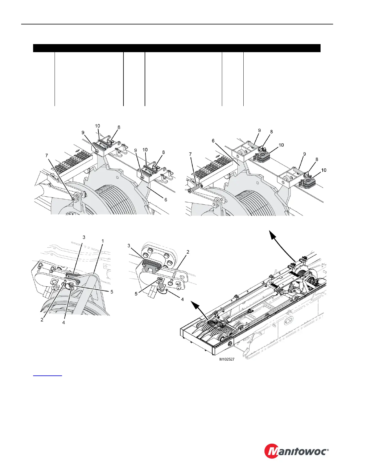
See Figure 4-27 for the following procedure.
13. Proceed as follows on both sides of the boom hoist
equalizer (1, View C):
a. Remove the quick-release pin (2, View C) and the
shims (3) from the shipping position.
b. Store the pin (2, View D) and the shims (3).
c. Remove the safety pin (4, View C) and the pin (5)
from the shipping position.
d. Store the pin (5, View D) and the safety pin (4).
14. Proceed as follows at the boom hoist (6, View A):
a. Remove the pin (7, View A) from the shipping
position.
Item Description Item Description Item Description
1 Boom Hoist Equalizer 8 Safety Pin 15 Hydraulic Hose (2)
2 Quick-Release Pin 9 Pin 16 Hydraulic Couplers (2)
3 Shims 10 Shims 17 Electric Cable (WRM1)
4 Safety Pin 11 Hydraulic Hose (5) 18 Receptacle (WRR1-J3)
5 Pin 12 Hydraulic Couplers (5) 19 Camera Switcher
6 Boom Hoist (Drum 4) 13 Electric Cable 20 Ground Cable (from mast)
7 Pin with Safety Pin 14 Receptacle (WRC3) 21 Ground Screw (on rotating bed)
Figure 4-27
View A SHIPPING
View B WORKING
View D
WORKING (2 places)
View C
SHIPPING (2 places)