Manitowoc Published 11-20-19, Control # 234-19 4-73
MLC300 OPERATOR MANUAL SETUP AND INSTALLATION
Install Counterweight Boxes
See Figure 4-52 for the following procedure.
NOTE The counterweight boxes (2) must be installed with
an assist crane.
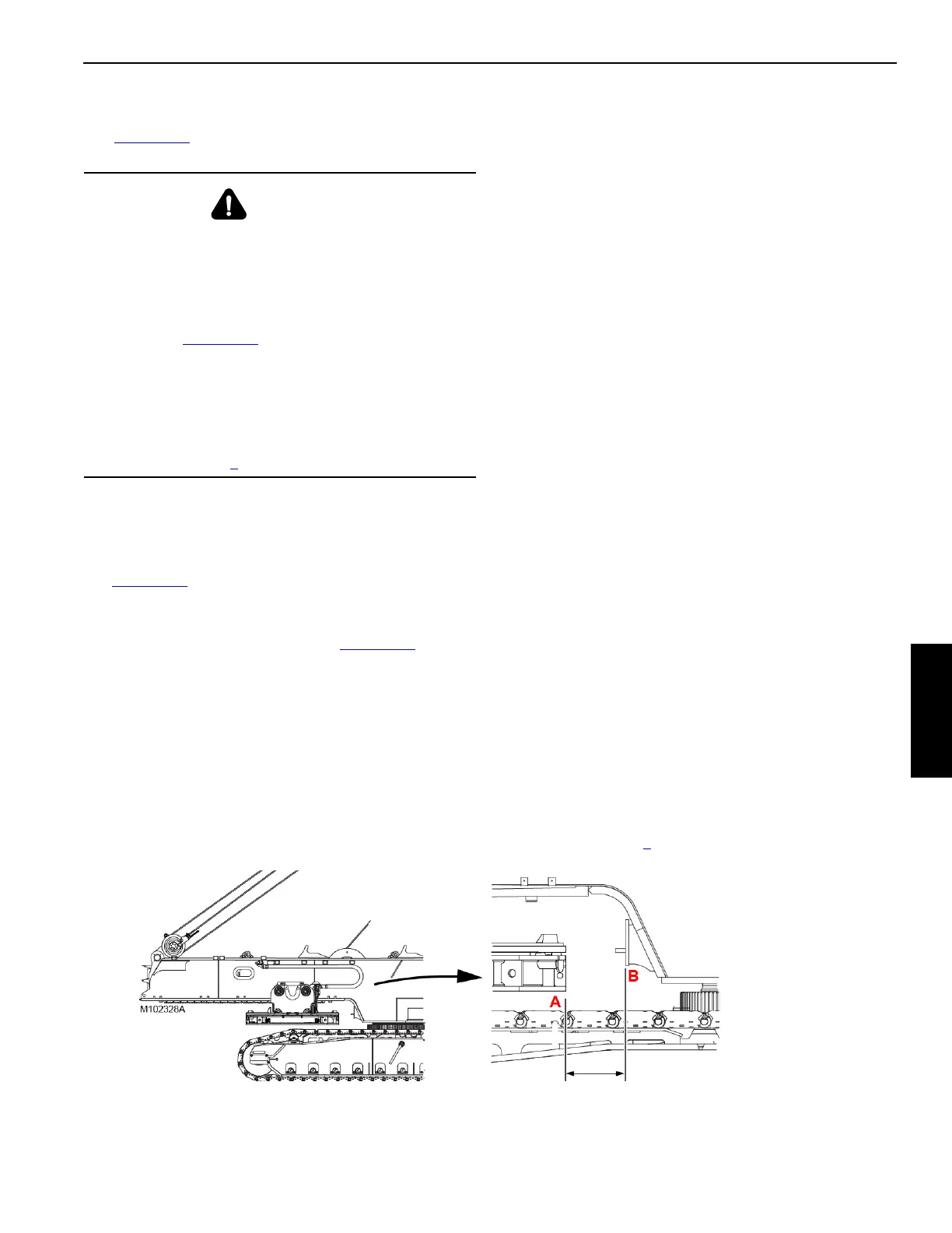
1. Travel the VPC trolley forward using the switch on the
remote control until the distance from the front edge (A,
Figure 4-53
) of the counterweight tray to the edge (B) of
the rotating bed is no more than the dimension given.
2. Install the desired number of counterweight boxes (see
Counterweight Series table in Figure 4-52
) in the
following sequence:
a. One counterweight box installed on either side of
the tray.
b. Two counterweight boxes installed on the other side
of the tray.
c. Continue installing the counterweight boxes in an
alternating sequence, two boxes at a time.
d. Finally, install one counterweight box on the
required side so that both stacks have an equal
number of boxes.
Note that a difference of not more than one counter-
weight box must be maintained side-to-side during
disassembly
3. Attach synthetic lifting slings (3, View E) around the
lifting lugs (4) on the counterweight boxes (2). Two
boxes may be lifted at one time.
4. Boom, swing, and hoist as necessary to position the
counterweight boxes on the desired side of
counterweight tray.
5. Lower the boxes so that the alignment lug (5, View F) on
the tray or box engages the notch on the adjacent box.
6. Disconnect the lifting slings.
7. Repeat the steps until the required number of boxes are
installed.
8. When all boxes have been installed, secure them as
follows:
a. Wrap the counterweight chain assembly (7, View B)
around the lifting lugs (4) on the counterweight
boxes and the counterweight tray lug (8).
The counterweight chain assemblies are designed
to minimize counterweight movement during travel
and operation permitted by Manitowoc’s operating
instructions.
b. Adjust the position of the chain so the turnbuckle (9,
View B) handle is accessible between two lifting
lugs (4).
c. Pull the chain tight by hand and attach the free end
of the chain to the connector (10, View C).
d. Tighten the turnbuckle until the counterweight chain
assembly is snug.
NOTE The ratchet on the turnbuckle must be flipped in one
direction to tighten the turnbuckle and in the opposite
direction to loosen the turnbuckle.
e. Secure the excess chain with the safety pin (11,
View D).
f. Repeat step 8
at the remaining three locations.
WARNING
Crush Hazard!
To prevent the crane from tipping and the counterweight
boxes from falling off the tray during assembly:
• Do not install (or remove) the counterweight boxes
until the counterweight tray is traveled to the position
shown in Figure 4-53
. The crane will tip.
To prevent the counterweight boxes from falling and
crushing personnel:
• Do not lift more than two boxes at a time. The lifting
lugs may break resulting in the boxes falling.
• Install the counterweight boxes in the sequence
specified in step 2
of this procedure.
Figure 4-53
Not More Than
375 mm (14-3/4 in