Manitowoc Published 11-20-19, Control # 234-19 4-17
MLC300 OPERATOR MANUAL SETUP AND INSTALLATION
Deploy Operator Cab
See Figure 4-13 for the following procedure.
1. If not already done, raise the operator cab (1) to the level
position using the remote control.
2. Remove the hitch pin (2, View A) from the shipping
position.
3. Remove the pin (4, View A) to disconnect the turnbuckle
(5) from the shipping lugs (6) on the rotating bed (7).
4. Rotate the operator cab (1) to the operating position.
5. Install the hitch pin (2, View B) in the operating position.
6. Using the pin (4, View B) pin the turnbuckle (5) to the
operating lugs (8) on the rotating bed (7).
Deploy Cab Rear Platform
See Figure 4-13 for the following procedure.
1. Support the cab rear platform (9, View C) so it cannot
fall. It weighs 30 kg (66 lb).
2. Remove the quick-release pins (10, View C) from the
shipping position and lower the platform to the operating
position (View D).
3. Install the quick-release pins (10, View D) to secure the
platform in the operating position.
4. Attach the handrail (11) to the cab rear platform (9, View
E) with the safety pins (12).
NOTE The handrail and cab rear platform have matching
identification numbers (13).
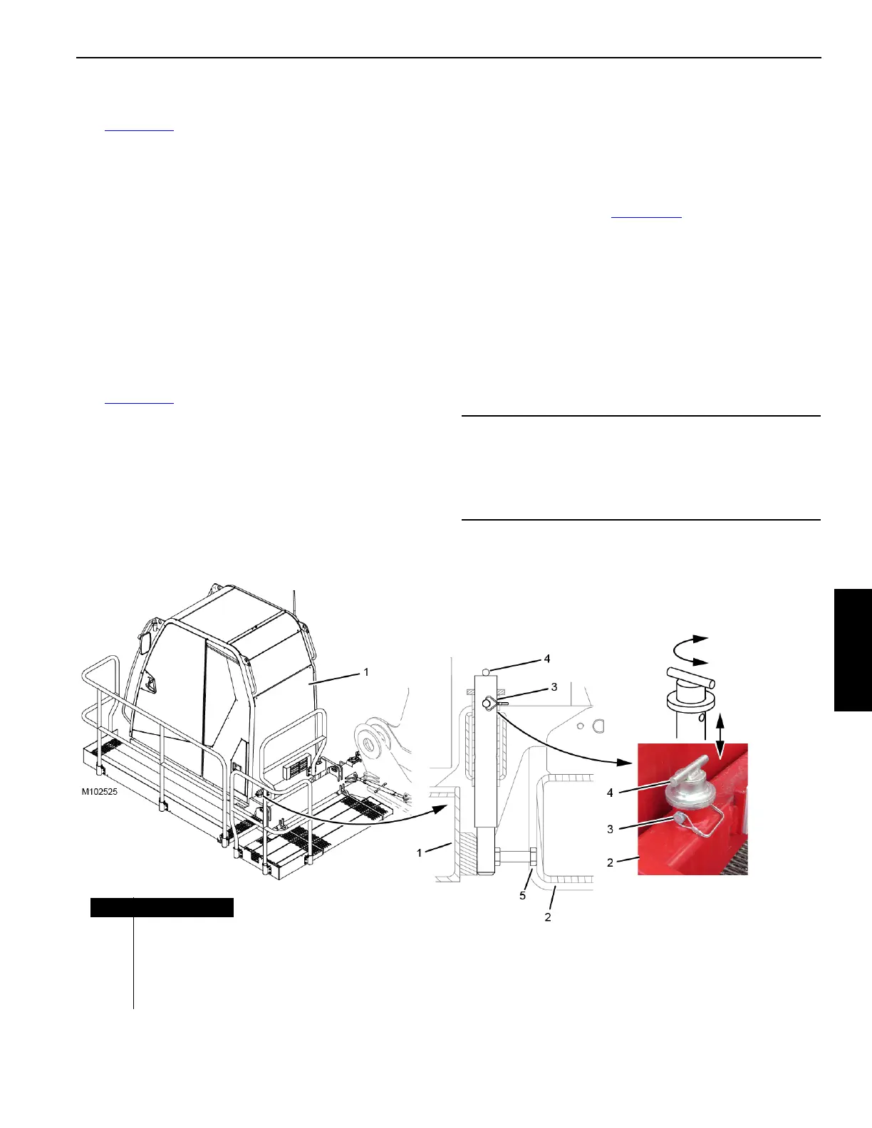
Move Cab Tilt Stop Pins to Working Position
The cab tilt stop pins (4, Figure 4-14) will be in the shipping
position when the crane arrives at the job site.
After the cab and platforms are deployed, proceed as
follows:
1. Tilt the cab (1) up a few degrees above horizontal.
2. Remove the safety pins (3).
3. Lower the stop pins (4) and rotate them to align the
connecting holes in the working position.
4. Install the safety pins (3).
CAUTION
The cab tilt stop pins must be in the working position for
crane operation.
The cab will hit the crawlers and be damaged when the
crane is swung if the cab is tilted down below horizontal.
Item Description
1Cab
2 Cab Support
3 Safety Pin (2)
4 Stop Pin (2)
5Stop Bolt
Figure 4-14
WORKING
Position
SHIPPING
Position
WORKING Position
Two Places