SETUP AND INSTALLATION MLC300 OPERATOR MANUAL
4-10
Published 11-20-19, Control # 234-19
PIN AND CONNECTING HOLE
CLEANLINESS
To prevent dirt from damaging closely machined surfaces of
pins and connecting holes:
• Thoroughly clean all pins and connecting holes.
• Apply a light coat of grease to all pins and connecting
holes.
HOSE AND CABLE CLEANLINESS
To prevent dirt from entering the hydraulic systems or from
damaging the electric connectors:
• Thoroughly clean the hydraulic fittings and the electric
connectors before connecting them.
• Thoroughly clean the dust caps before attaching them to
hoses, tubes, or cables.
• Do not drag the hydraulic hose fittings, the hydraulic
hoses, the electric cable connectors, or the electric
cables on the ground.
NOTE Apply a light coat of silicone lubricant to the threads
of all dust caps, couplers, and connectors to help in
preventing the threads from seizing.
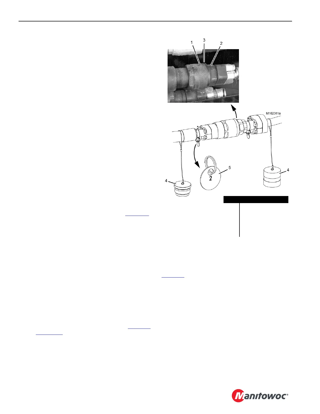
HYDRAULIC HOSE IDENTIFICATION
Where necessary, the hydraulic hoses and corresponding
couplers have identification tags as shown in Figure 4-8
.
Match the number on the hose with the number on the
corresponding coupler to ensure proper connection.
CONNECTING/DISCONNECTING
HYDRAULIC HOSES AND ELECTRIC
CABLES
Always STOP ENGINE before performing the following
steps during crane assembly and disassembly:
• Connecting and disconnecting hydraulic lines. It will be
easier to connect and disconnect the couplers when
there is no pressure in the system.
• Connecting and disconnecting electric cables. The
potential for operating faults or damage to the electric
components exists if the engine is not stopped.
NOTE To stop the engine if it was started from the remote
control, turn the external engine switch (8, Figure 4-7
on page 4-8) COUNTERCLOCKWISE to the STOP
position.
To stop the engine if it was started from the cab, use
the ignition switch in the cab.
TIGHTENING HYDRAULIC COUPLERS
Connect each screw-to-connect coupler and nipple
(Figure 4-8
) as follows:
1. Lubricate coupler (1) threads, nipple (2) threads, and
nipple O-ring (3) with LPS-2 Aerosol Lubricant.
2. Hand tighten coupler (1) onto nipple (2).
3. Using opened-end wrenches, tighten the coupler until
there is metal-to-metal contact between the coupler and
the nipple. O-ring (3) must not be visible.
To avoid damage, do not exceed a torque of:
• Size -06 = 1.62 lbf ft (2,2 Nm)
• Size -08 = 1.33 lbf ft (1,8 Nm)
• Size -12 = 4.13 lbf ft (5,6 Nm)
• Size -20 = 6.04 lbf ft (8,2 Nm)
• Size -24 = 19.16 lbf ft (26,0 Nm)
Figure 4-8
Item Description
1 Coupler
2 Nipple
3 O-ring (not visible)
4Dust Cap
5 Identification Tag