Manitowoc Published 11-20-19, Control # 234-19 4-35
MLC300 OPERATOR MANUAL SETUP AND INSTALLATION
b. Store the pin (7, View B).
15. Proceed as follows (two places) at the boom hoist (6,
View A):
a. Remove the safety pin (8, View A) and the pin (9)
from the shipping position.
b. Store the pin (9, View B) and the safety pin (8).
c. Remove the shims (10, View A) from the shipping
position.
d. Store the shims (10, View B).
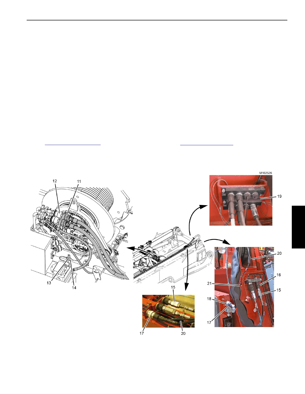
16. Disconnect the dust caps from four hydraulic couplers
(12, View E) on the boom hoist.
17. Connect four hydraulic hoses (11, View E) to four
hydraulic couplers (12) on the boom hoist (6).
• The hoses are attached to storage couplers on the
right inboard side of the rotating bed. See
Figure 4-95 on page 4-141
.
• Match the identification numbers on the hoses with
the identification numbers on the couplers for proper
connection.
• Connect the dust caps to the storage couplers.
18. Connect the electric cable (13, View E) from the rotating
bed to the receptacle (14) on the boom hoist.
19. Connect the two hydraulic hoses (15, View G) from the
live mast to the two hydraulic couplers (16) on the
rotating bed.
The hydraulic hoses (15) the electric cable (17) and the
ground cable (20) are stored on the live mast as shown
in View H.
20. Connect the electric cable (17, View G) from the live
mast to the receptacle (18) on the rotating bed.
21. Attach the ground cable (20, View G) from the live mast
to the rotating bed with the ground screw (21) and
washer.
22. Connect the Drum 2/3 camera cable from the live mast
to the camera switcher (19, View F) on the rotating bed.
See Figure 4-30 on page 4-41
.
View E
View F
View G
Figure 4-27 continued
View H
SHIPPING