SETUP AND INSTALLATION MLC300 OPERATOR MANUAL
4-64
Published 11-20-19, Control # 234-19
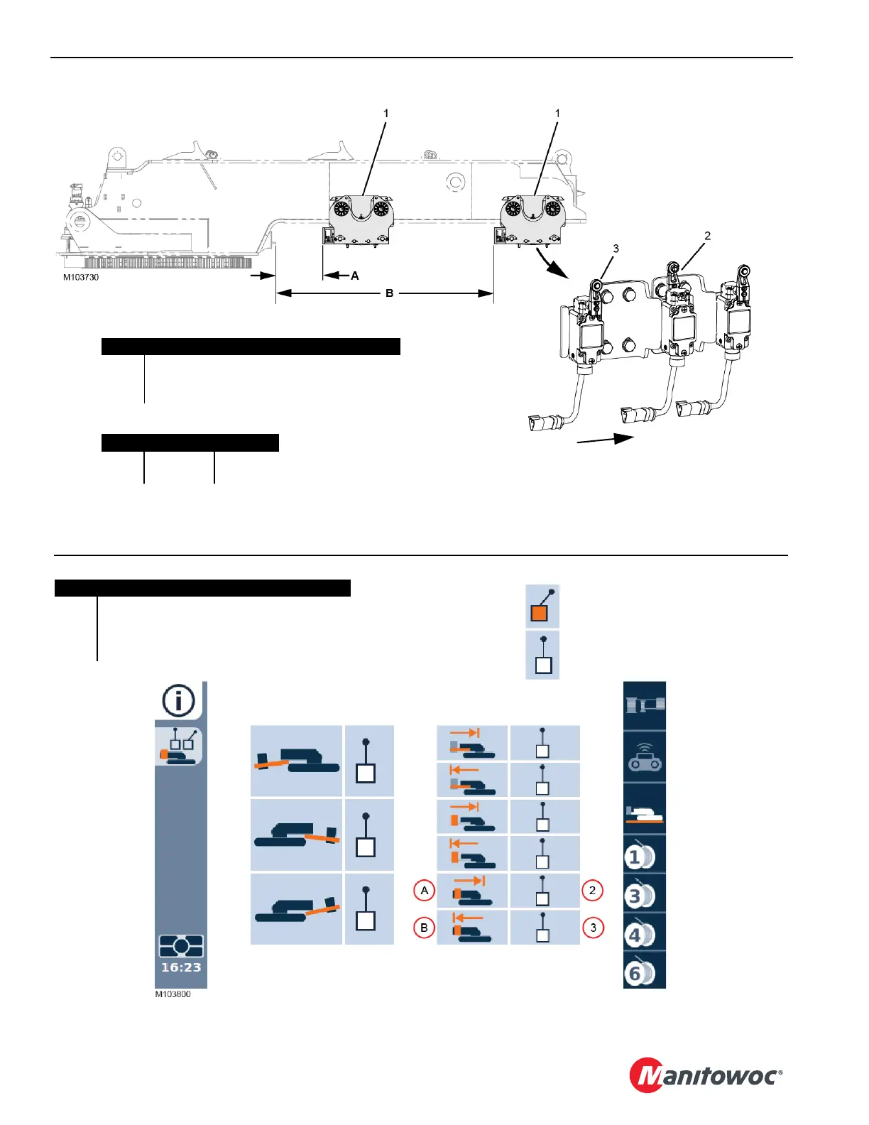
FIGURE 4-46
Item Description
1VPC Trolley
2 Limit Switch: VPC Trolley Minimum Position
3 Limit Switch: VPC Trolley Maximum Position
Dimension
A 1 000 mm 39.37 in
B 3 915 mm 154.13 in
View of Limit Switches Looking
Outward through Left Access
Hole in Bottom of VPC Trolley
FRONT of Crane
FIGURE 4-47
Item Description
A VPC Trolley Minimum Position
B VPC Trolley Maximum Position
2 Limit Switch: VPC Trolley Minimum Position
3 Limit Switch: VPC Trolley Maximum Position
Limit Switch TRIPPED
Limit Switch NOT TRIPPED