Figure 4-60
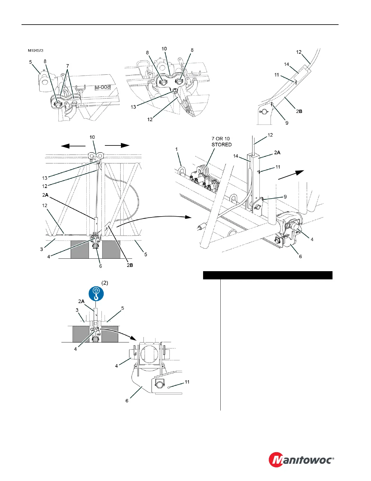
Item Description
1 Lifting Lug (2)
2 Socket (2)
3 Insert (closest to butt)
4 Connecting Pin with safety pins (2)
5 Adjacent Insert
6 Drop-Down Suspension Beam Assembly
7 Standard Strap Links (4)
8 Pin with Collar, Retaining Pin and Cotter Pins (4)
9 Hitch Pin with Hair-Pin Cotter, 235 mm (2)
10 Strap Links (4)
11 Hitch Pin with Hair Pin Cotter, 196 mm (2)
12 Drop-Down Suspension Pendant (2)
13 Pin with Cotter Pin (2)
14 Button (10 each pendant)
A Working Position
B Pendant Installation Position
View A
View B
View C
View D
View F
View E
Butt
Top
Top