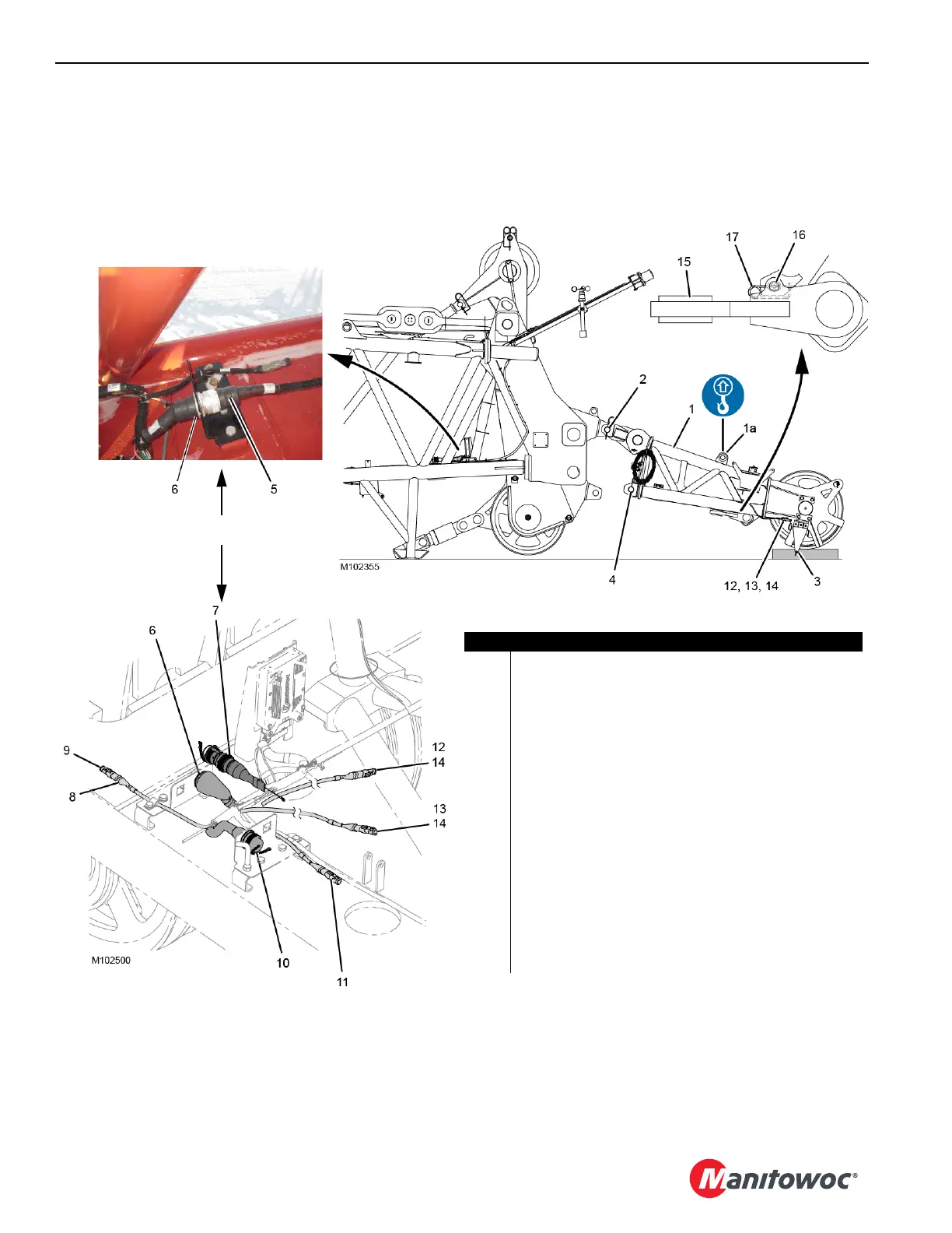
Figure 4-67
Item Description
1 Upper Boom Point
1a Lifting Lug (if equipped)
2 Pins with Safety Pins (2)
3 Block-Up Limit Lug
4 Pins with Safety Pins (2)
5 Electric Cable
6 Receptacle - ATTACHMENTS
7 Shorting Plug
8 Electric Cable - CAN NET OUT
9 Terminator Plug
10 Electric Cable - POWER from Boom Cable Reel
11 Electric Cable - CAN NET IN from Boom Cable Reel
12 Electric Cable - Lower Block-Up Limit Stop Switch
13 Electric Cable - Lower Block-Up Limit Slowdown Switch
14 Shorting Plug (4)
15 Dead-End Link (stored)
16 Pin
17 Safety Pin
View A
View B
OR