Figure 4-112
OR
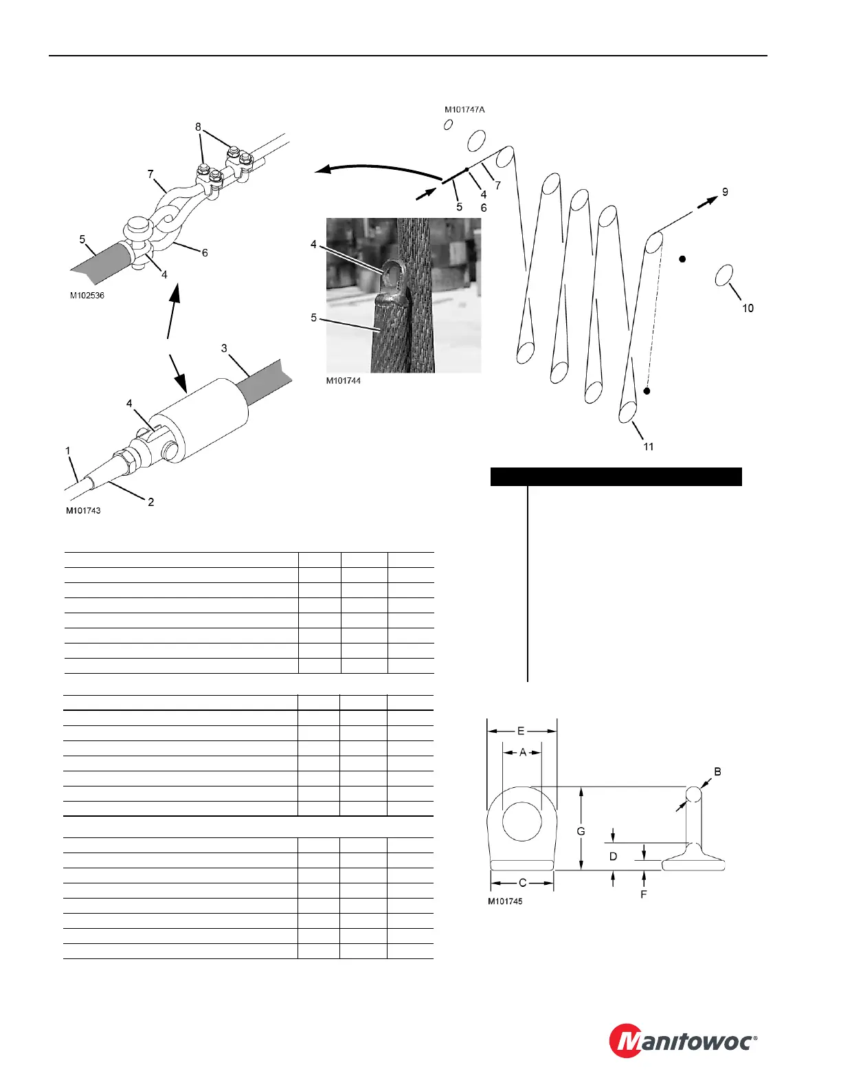
Item Description
1 Rigging Line
2 Connector
3 Wire Rope with Button
4 Pad Eye
5 Wire Rope without Button
6 Shackle
7 Rigging Line
8 Rope Clips
9 Pull Rigging Line with Winch or Forklift
10 Boom Point Sheaves
11 Load Block Sheaves EXAMPLE
No. 1.5 Pad Eye Item mm Inch
Approximate Capacity 553 kg (1220 lb) A 16,00 5/8
B 6,35 1/4
C 25,40 1
D 11,18 7/16
E 28,70 1-1/8
F 4,06 1/16
G 33,27 1-5/16
No. 1 Pad Eye Item mm Inch
Approximate Capacity 553 kg (1220 lb) A9,653/8
B6,351/4
C 22,40 7/8
D 10,40 13/32
E 22,40 7/8
F3,301/8
G 25,40 1-1/32
No. 2 Pad Eye Item mm Inch
Approximate Capacity 1 179 kg (2600 lb) A 19,05 3/4
B9,653/8
C 26,92 1-1/16
D 12,70 1/2
E 38,10 1-1/2
F4,833/16
G 41,26 1-5/8