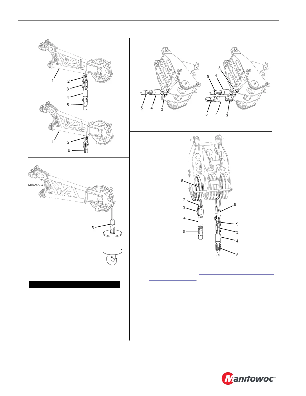
Figure 4-116
Upper Boom Point
Multiple Parts of Line
Upper Boom Point
Single Part of Line
One Drum Reeving
Lower Boom Point — PAST
Item Description
1 Upper Boom Point
2 Dead-End Link
3Link
4Swivel
5 Button Socket – 28 mm or 32 mm
6 Sheave Cluster
7 Dead-End Link
8 Pendant: 3,2 m (10 ft 7-1/4 in) Long
9 Dead-End Link
Two Drum Reeving
Lower Boom Point
CURRENT
NOTE The location of the sheave cluster (6) can vary depending on
reeving. See the Reeving Diagrams at the end of this section for
dead-end locations. See
Remove/Install Lower Boom Point
Sheaves on page 4-93.
The pendant (8) and dead-end link (9) have two uses:
• Tandem drum reeving. The pendant and link must be installed
around the sheave that is symmetric about the centerline of the
boom top with the dead-end link (7).
• They can be used to improve the block-up distance from the
boom top to the load block for single drum reeving.
The pendant (8) is stored in the boom butt. The dead-end link (9) is
stored in the parts box.