Home
Manitowoc
Construction Equipment
MLC300
Manitowoc MLC300 User Manual
5
of 1
of 1 rating
332 pages
Give review
Manual
Specs
To Next Page
To Next Page
To Previous Page
To Previous Page
Loading...
Manitowoc
Published 1
1-20-19, Control # 234-19
3-5
MLC300 OPERATOR MANUAL
OPERAT
ING CONTROLS AND PROCEDURES
3
1
3
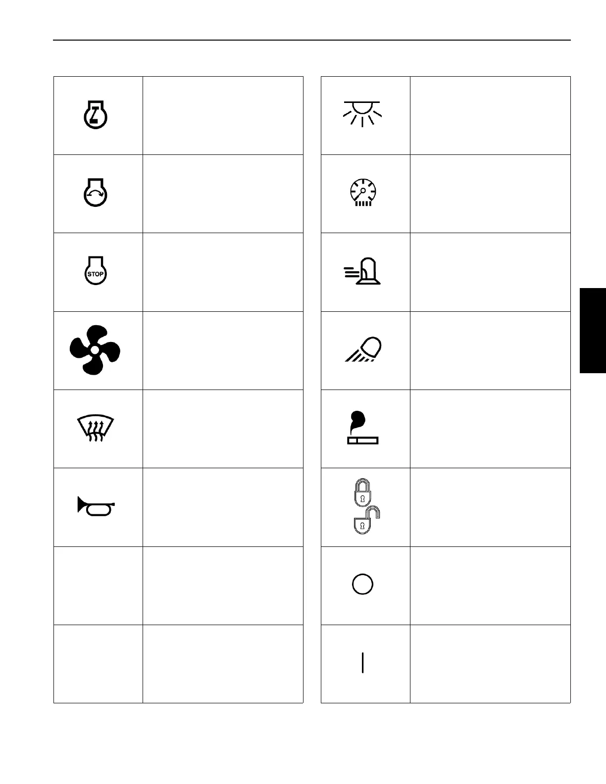
Engine Run
Light, Dome
Engine Start
Light, Consoles
Engine Stop
Light, Position
Fan
Light, Work
(and camera)
Heater
Lighter
Horn
Lock and
Unlock
Off
On
T
able 3-2.
Symbol Identifi
cation —
Control Consoles
M1
0015
9
M103338
M100160
M100165
M100161
M100291
M100142
M100166
M100163
M100167
M100164
M100162a
M100170
M100171
56
58
Table of Contents
Default Chapter
5
Table of Contents
5
Section 1
13
Crane Data
13
Crane Weights
13
Outline Dimensions
13
Change of Ownership Registration
13
Manitowoc Dealer
13
Crane/Attachment Identification
13
Crane Orientation
13
Identification and Location of Components
15
English and Metric Conversions
18
Direct Conversion
18
Inverse Conversion
18
Section 2
21
Continuous Innovation
23
Nameplates and Decals
23
Safety Messages
23
General
23
Safety Alert Symbol
23
Signal Words
23
Symbol Identification
23
Safety and Information Signs
25
Maintaining Signs
25
Ordering Signs
25
Crane Access Points
28
General
28
Getting on or off Crane
28
Personal Fall-Protection
29
Operator Manual/Capacity Chart Storage
30
General
30
Storing Manuals
30
Safe Operating Practices
31
General
31
Read Operator Manual
31
Operator Qualifications
31
Operator Conduct
31
Handling Load
33
Size of Load
33
Attaching Load
33
Lifting/Moving Load
34
Multiple Load Line Operation
35
Signals
36
Holding Load
36
Safety Devices
37
Operational Aids
37
Category 1 Operational Aids
37
Category 2 Operational Aids
38
Assembling, Disassembling, or Operating Crane Near Electric Power and Transmission Lines
39
Electrocution Hazard
39
Set-Up and Operation
39
Electrocution Hazard Devices
40
Electrical Contact
40
Refueling
41
Fire Extinguishers
41
Accidents
41
Safe Maintenance
41
Maintenance Instructions
41
Safe Maintenance Practices
41
Environmental Protection
43
Boom Disassembly Safety
45
General
45
Location
45
Pin Removal
45
Disassembly Precaution
45
Personnel Handling Policy
46
Pedestal/Barge Mounted Cranes
47
Pedestal Mounted Crane
48
Barge Mounted Crane
48
Definition
48
Examples
48
Capacity Charts for Barge Mounted Crane
49
Shock Loading Caused by Barge Dynamics
49
Operation on Barge
49
Barge Mount Definitions
50
Inspection of Barge-Mounted Crane
50
Transporting Crane on Barge
50
Section 3
51
Standard Hand Signals for Controlling Crane Operations
54
Symbols Used on Control Consoles
56
Symbols Used on Remote Control
59
Operating Controls
62
Left Console
66
Right Console
68
Seat Controls
80
Climate Control Keypad
81
Other Operator Aids
82
Boom Angle Indicator
82
Crane Capacity Beacons
82
Upperworks Level
82
Crane Cameras
84
Crane Camera Monitor
85
Motion Warning Lights and Alarms
86
Service Lights
88
Remote Control Activation
90
Remote Control Operation
92
Operating Limits Identification and Operation
98
Bypassing Limits in Luffing Jib Setup Mode
104
Resetting Luffing Jib Limits
105
Drum and Control Handle Identification
106
Right Cab Window Operation
109
Closing Window
109
Opening Window for Ventilation
109
Operator Cab Emergency Exit
109
Cab Door Adjustment
109
Cab Tilt Stop Pins Installation
109
Cab Tilt Speed Adjustment
109
Ladder Installation (Past)
111
Installing Ladder
111
Storing Ladder
111
Using Ladder (Working Position)
111
Removing Ladder
111
Ladder Installation (Current)
113
Installing Ladder
113
Storing Ladder
113
Using Ladder (Working Position)
113
Removing Ladder
113
Operating in Wind
114
Crawler Blocking
114
Intermediate Suspension
114
Preparing Crane for Operation
115
Startup Procedure
115
Operating Procedures
119
VPC Operation
119
Boom Hoist Operation
120
Luffing Hoist Operation
121
Swing Operation
122
Load Drum Operation (Without Free Fall or with Free Fall Disabled)
125
Load Drum Operation (with Free Fall Enabled)
127
Free Fall Brake Pedal Hydraulic Pressure Test
129
Free Fall Brake Operational Test
129
Clamshell Operation
130
Preparing for Clamshell Operation
130
Clamshell Operation in Full-Power
130
Travel Operation
132
Shutdown Procedure or Leaving the Crane Unattended
134
Changing Counterweight with Boom/Jib in Air
135
Vpc
135
Vpc-Max
135
Cold Weather Operation
137
Crane Limitations
137
Wire Rope
137
Cold Weather Starting Aid
137
Cooling System
137
Batteries
137
Engine Oil, Gear Oil, and Hydraulic Oil
137
Cold Weather Heater Package
139
Turning Heaters on
139
Turning Heaters off
139
AC Operation
141
Installing APU
141
Turning on AC Powered Components
141
Turning off AC Powered Components
141
Removing APU
141
Section 4
147
Boom and Jib Assembly Drawings
147
Liftcrane Mast Capacities
147
Optional Attachments
147
General Safety
147
Crane Orientation
147
Assembly and Disassembly Notes
148
Assembly and Disassembly Area
148
Accessing Parts
148
Personal Fall-Protection
149
Handling Components
149
Retaining Connecting Pins
149
Crane Weights and Shipping Data
149
Parts Box
150
Self-Erect Components
150
Remote Control
154
Activating Remote Control
155
Starting Engine with Remote Control
155
Setup Mode
155
Pin and Connecting Hole Cleanliness
156
Hose and Cable Cleanliness
156
Hydraulic Hose Identification
156
Connecting/Disconnecting Hydraulic Hoses and Electric Cables
156
Tightening Hydraulic Couplers
156
Pre-Start Checks
157
Electric System
157
Engine
157
Gear Boxes
157
Hydraulic System
157
Swing Limits
159
Crane Assembly
161
Start Engine
161
Raise Operator Cab
161
Remove Carbody-Rotating Bed Module from Trailer
161
Deploy Cab Rear Platform
163
Move Cab Tilt Stop Pins to Working Position
163
Remove Window Covers
165
Raise RCL Light to Working Position
165
Deploy Right Side Rear View Mirror
165
Move Rotating Bed Left-Front Platform to Working Position
167
Move Rotating Bed Left-Front Ladder to Working Position
167
Install Rotating Bed Handrails
169
Deploy Rotating Bed Left-Rear Platform
169
Deploy Valve Cover Platforms
169
Deploy Exhaust Shield
169
Using Rotating Bed Left-Rear Ladder (Past)
171
Using Rotating Bed Left-Rear Ladder (Current)
173
Remove Live Mast Package from Trailer
175
Install Live Mast Package
179
Install Drum 3
183
Install Drum 2
183
Camera Connections
187
Activate Setup Mode
188
Raise Live Mast to Operating Position
188
Live Mast Operating Precautions
189
Attach Lifting Slings to Self-Erect Cylinder
190
Lubricate Crawler-To-Carbody Machined Surfaces
191
Install First Crawler
193
Install Second Crawler
197
Install Crawler Ladders
197
Store Carbody Jacks
199
Install Carbody Front and Rear Platforms
199
Deploy Carbody Side Platforms
201
Prepare VPC Trolley
203
Install VPC Trolley
205
VPC Trolley Limit Switch Checks
211
Remove Counterweight Tray from Trailer
213
Remove Counterweight Boxes from Trailer
213
Assemble Boom and Jib
213
Prepare Counterweight Tray
215
Install Counterweight Tray
217
Install Counterweight Boxes
219
Boom and Jib Rigging - General
220
Assist Crane Requirements
220
Blocked Crawlers
221
Boom Handling with Mast
221
Assembly Drawings
221
Identifying Boom and Jib Components
221
Handling Components
223
Boom #500 Assembly
225
Assemble Boom Inserts
225
Install Intermediate Wire Rope Guide
229
Install Drop-Down Suspension
231
Install Boom Top
233
Raise Boom Top Wire Rope Guide
235
Install Position Light and Wind Speed Indicator
235
Connect Boom Top Electric Cables
235
Connect Boom Straps
237
Install/Remove Lower Boom Point
239
Remove/Install Lower Boom Point Sheaves
239
Install Upper Boom Point
241
Connect Terminator/Shorting Plugs at Boom Top
241
Connect Boom Butt to Crane
243
Connect Boom Butt to Boom
245
Connect Mast Straps to Boom Straps
247
Deactivate Setup Mode
247
Connect Hydraulic Hoses from Crane to Boom Butt
249
Connect Electric Cables from Boom Butt to Crane
249
Install Boom Top Camera and Connect Electric Cables
251
Install the Boom Load Lines
253
Install Boom Block-Up Limit Components
253
Prepare Intermediate Suspension Pendants
255
Raise Boom
256
Pre-Raising Checks
256
Boom Raising Procedure
256
Shipping Crane Components
257
Crane Disassembly
258
Prepare Crane
258
Lower Boom
259
Remove Block-Up Limit Components
259
Store the Load Lines
259
Remove Boom Top Cameras
259
Disconnect Boom Butt Electric Cables
259
Disconnect Boom Butt Hydraulic Hoses
259
Activate Setup Mode
261
Disconnect Mast Straps from Boom Straps
261
Disconnect Boom Butt from Boom
263
Disconnect Boom Butt from Crane
265
Disassemble Boom
267
Remove Counterweight Boxes
269
Remove Counterweight Tray
271
Remove VPC Trolley
273
Prepare VPC Trolley for Shipping
277
Store Carbody Side Platforms
279
Remove Carbody Front and Rear Platforms
279
Prepare Crawlers for Removal
279
Deploy Carbody Jacks
279
Remove First Crawler
281
Remove Second Crawler
283
Remove Lifting Slings from Self-Erect Cylinder
283
Lower Live Mast to Transport Position
285
Remove Drum 2
287
Remove Drum 3
287
Install/Store Rotating Bed Platforms
287
Remove Live Mast Package
288
Install Live Mast Package on Trailer
295
Store Rotating Bed Left-Rear Platform and Handrails
299
Remove Rotating Bed Handrails
299
Remove Rotating Bed Left-Rear Ladder
299
Move Rotating Bed Left-Front Ladder to Working Position
301
Move Rotating Bed Left-Front Platform to Working Position
301
Store Right Side Rear View Mirror
303
Store RCL Light
303
Move Cab Tilt Stop Pins to Shipping Position
303
Store Cab Rear Platform
303
Secure Operator Cab
303
Install Window Covers
303
Install Carbody-Rotating Bed Module on Trailer
305
Store Remote Control
305
Final Checks
305
Wire Rope Installation
307
Wire Rope Specifications
307
Wire Rope Storage
307
Seizing and Cutting Wire Rope
307
Anchoring Wire Rope to Drum
308
Winding Wire Rope Onto Drum
308
Anchoring Wire Rope to Wedge Socket
311
Anchoring Wire Rope to Button Socket
311
Pad Eye Usage for Wire Rope Reeving
313
Breaking in Wire Rope
313
Rigging Winch Operation
314
Selecting Rigging Winch Mode
314
Operating Rigging Winch
315
Load Line Reeving
317
Guide Sheaves and Drums
317
Dead End Locations
317
Load Block Identification
317
Duplex Hook
317
Wire Rope Specifications
317
Load Block Reeving
317
Load Block Tieback
319
General
319
Specifications
319
Section 5
321
Lubrication
321
Lube and Coolant Product Guide
323
Section 6
327
Inspection and Maintenance Checklist
327
Fiberglass Maintenance
327
Other manuals for Manitowoc MLC300
Service And Maintenance Manual
280 pages
Guide
36 pages
Manual
211 pages
Product Guide
36 pages
5
Based on 1 rating
Ask a question
Give review
Questions and Answers:
Need help?
Do you have a question about the Manitowoc MLC300 and is the answer not in the manual?
Ask a question
Manitowoc MLC300 Specifications
General
Brand
Manitowoc
Model
MLC300
Category
Construction Equipment
Language
English
Related product manuals
Manitowoc MLC650
360 pages
Manitowoc MLC100-1
218 pages
Manitowoc MLC165-1
256 pages
Manitowoc VPC-MAX MLC650
234 pages
Manitowoc 2250
312 pages
Manitowoc 14000
270 pages
Manitowoc 888 Series
4 pages
Manitowoc Grove RT890E
24 pages
Manitowoc 14000 2 Series
4 pages
Manitowoc 14000 1 Series
6 pages
Manitowoc GROVE GMK5150L
1040 pages
Manitowoc Grove GMK 5250L
958 pages