Manitowoc Published 11-20-19, Control # 234-19 3-17
MLC300 OPERATOR MANUAL OPERATING CONTROLS AND PROCEDURES
Item Name Description
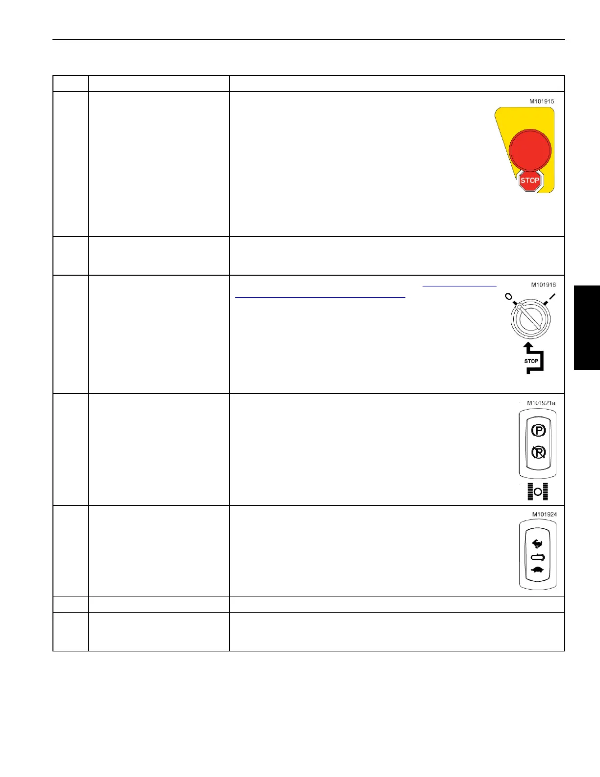
1 Emergency Stop Button
When this button is depressed, the crane engine shuts off,
the motor brakes apply, and the currently operated
functions come to a complete stop.
For normal engine shut down, use the engine ignition
switch.
NOTE The button must be pulled up before the engine can
be restarted.
If the emergency stop switch has been activated
while functions were being operated, test the
corresponding disk brakes for proper operation
before putting the crane back into service.
2
Rated Capacity Limiter (RCL)
and Rated Capacity Indicator
(RCI) Display
Displays load lifting information and alerts the operator to overload conditions.
See the RCL/RCI Operation Manual at the end of this section for detailed
information.
3 Limit Bypass Key Switch
This key bypasses the limits described in Operating Limits
Identification and Operation on page 3-46:
• To BYPASS an operating limit, turn the key to I and hold the
key in this position.
• To ENABLE operating limits, release the key to O. This
position allows a limit to stop a crane function in the normal
matter. The key must be in this position for all normal
operation. Otherwise, structural damage can occur.
Remove the key to prevent unauthorized operation.
4 Travel Park Switch
• Press the TOP of the rocker to PARK travel. With park on, the
travel control handles are inoperable and the travel brakes are
applied.
• Press the bottom of the rocker UN-PARK travel. With park off, the
travel control handles are operable and the travel brakes are
applied and released in conjunction with control handle
movement.
5 Travel Speed Switch
• Press the TOP of the rocker to operate the travel motors in HIGH
speed. High speed operation provides maximum available travel
speed for traveling long distances.
• Press the BOTTOM of the rocker to operate the travel motors in
LOW speed. Low speed operation provides smooth starts and
stops and allows more precise control of the travel motors than
high speed.
6 Not Used
7 Main Display
Displays operating conditions, faults, and diagnostic information. See the
MLC300 Main Display Operation Manual at the end of this section for detailed
information.
Table 3-6. Right Console
 Loading...


