Manitowoc Published 11-20-19, Control # 234-19 3-43
MLC300 OPERATOR MANUAL OPERATING CONTROLS AND PROCEDURES
32 I Control Handle
Controls the functions identified by this icon on the decals next to the
control handle.
33 Handle Indicator Light Glows BLUE when the control handle (32) is operated.
34 II Control Handle
Controls the functions identified by this icon on the decals next to the
handle.
35 Handle Indicator Light Glows BLUE when the control handle (34) is operated.
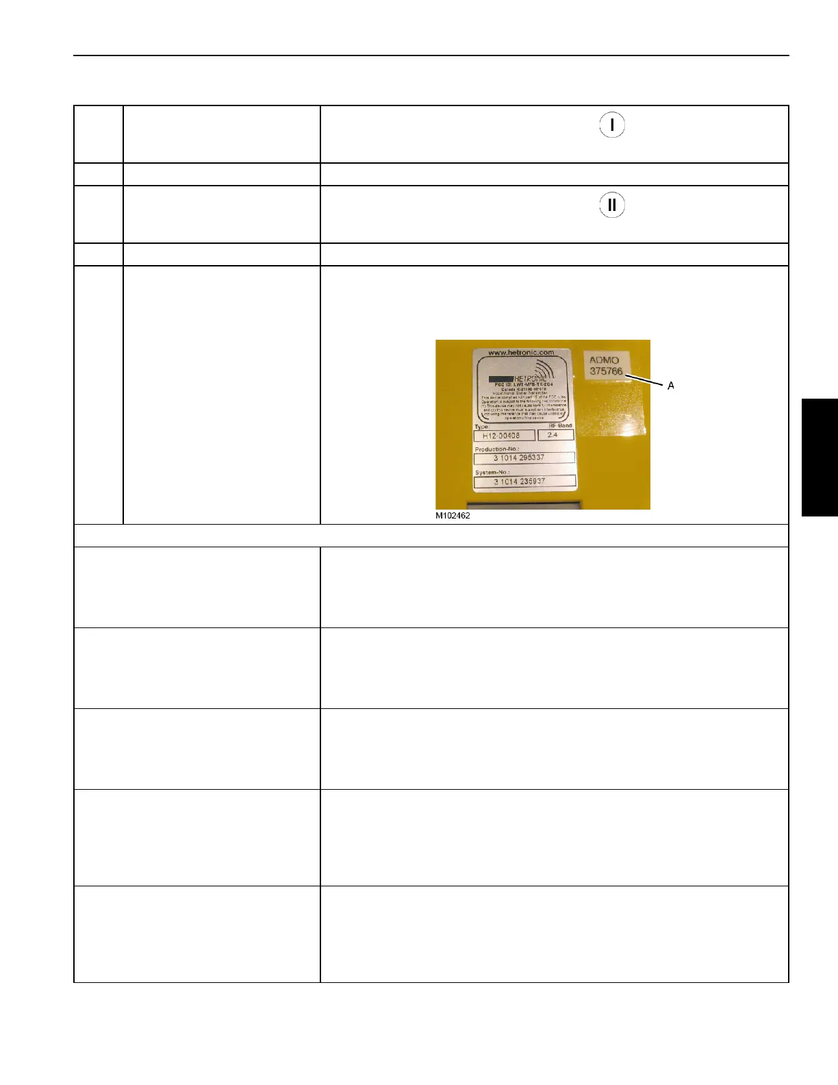
36 Identification Number
Each remote control has a unique identification number (A) on the side of the
unit. This number must be entered in the Main Display when turning on the
remote control in the Remote Control Selection Screen. See MLC300 Main
Display Operation Manual for instructions.
Setup Function Operation
Individual Carbody Jack
• Select and confirm item 10.
• Move the control handle I in the required direction to select the desired jack.
• Move the control handle II FORWARD to EXTEND the jack or move the
control handle II REARWARD to RETRACT the jack.
All Carbody Jacks (at same time)
• Select and confirm item 11.
• Move the control handle I either in direction to energize the function.
• Move the control handle II FORWARD to EXTEND all of the jacks or move
the control handle II REARWARD to RETRACT all of the jacks.
Cab Tilt
• Select and confirm item 12.
• Move the control handle I in either direction to energize the function.
• Move the control handle II FORWARD to EXTEND the cab tilt cylinder or
move the control handle II REARWARD to RETRACT the cab tilt cylinder.
Live Mast Hinge Pins
• Select and confirm item 13.
• Move the control handle I in either direction to energize the function.
• Move the control handle II FORWARD to ENGAGE the live mast hinge pins
or move the control handle II REARWARD to DISENGAGE the live mast
hinge pins.
Equalizer Hinge Pins
• Select and confirm item 14.
• Move the control handle I in either direction to energize the function.
• Move the control handle II FORWARD to ENGAGE the equalizer hinge pins
or move the control handle II REARWARD to DISENGAGE the equalizer
hinge pins.
Table 3-15. Identification and Operation of Remote Controls