OPERATING CONTROLS AND PROCEDURES MLC300 OPERATOR MANUAL
3-42
Published 11-20-19, Control # 234-19
10
Carbody Jacks, ALL jacks
operated at the same time.
The function light (9) glows GREEN next to the icon for the setup function that
has been selected.
* = past production
11
Carbody Jack – An individual
jack can be operated.
12 Cab Tilt
13 Live Mast Hinge Pins
14 Equalizer Hinge Pins
15 Live Mast Assist Arms
16 Crawler Pins, Left
17 Crawler Pins, Right
18 * Crawler Track Tensioner, Left
19 * Crawler Track Tensioner, Right
20
Trolley Travel, In/Out
(rotating bed mounted trolley)
21
Trolley Pins, Front
(rotating bed mounted trolley)
22
Trolley Pins, Rear
(rotating bed mounted trolley)
23 Boom Hinge Pins
24 Rigging Winch
25
Trolley Travel, In/Out
(beam mounted trolley)
26 Selector Switch
Move this switch UP or DOWN to scroll through the set up functions (10 through
25) until the green light appears next to the desired function.
27 Communication Light
Flashes GREEN to indicate that there is a good signal between the transceiver
and the remote control. If the signal is lost, troubleshoot the system (dead
battery or connection, faulty electric cable, faulty electric cable connection).
28 Fault Light
Glows RED to indicate that an operating limit has been exceeded. See MLC300
Main Display Operation Manual.
29 Fault Light
Glows AMBER to indicate that a system fault exists. See MLC300 Main Display
Operation Manual.
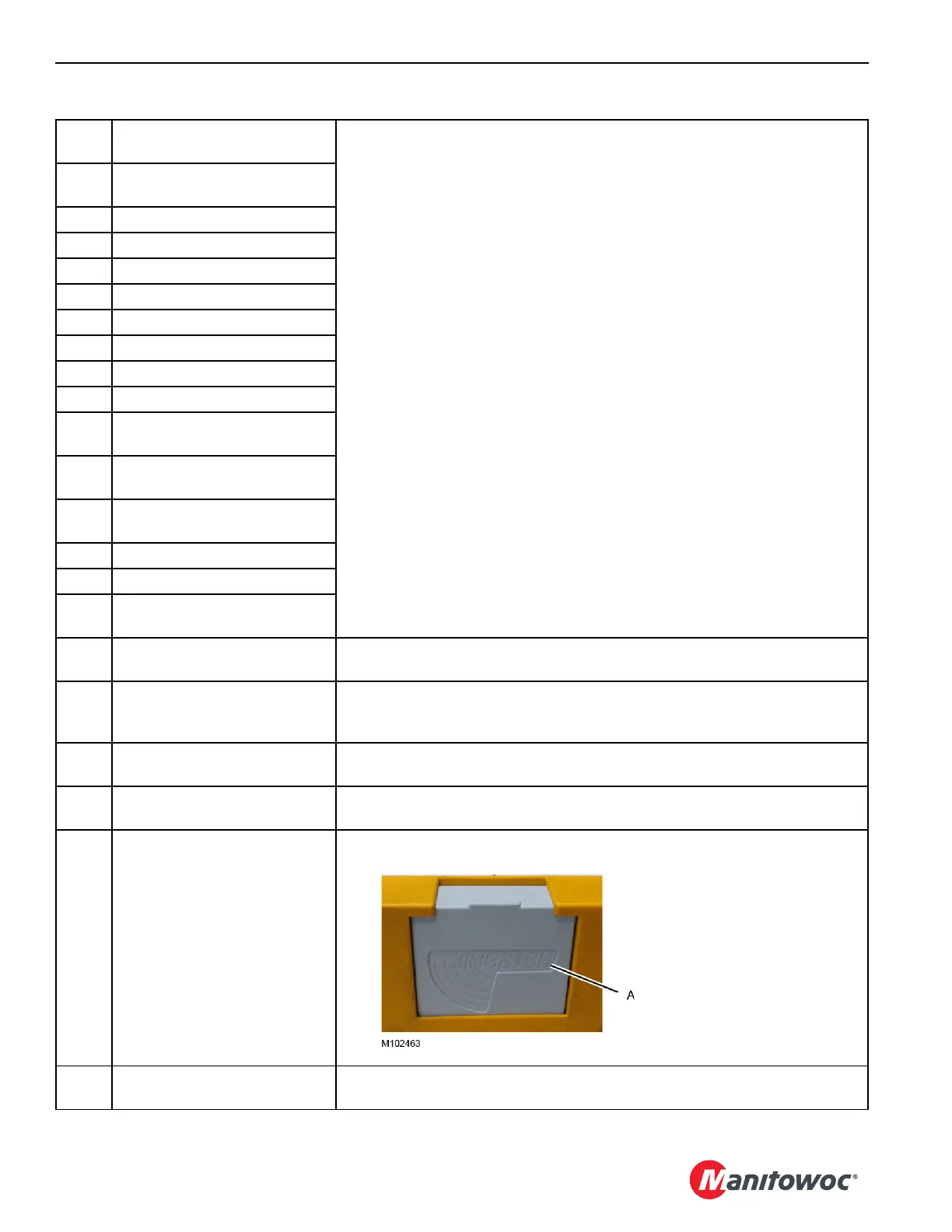
30 Battery Light
Glows RED when the remote control battery (A) is dead. Replace the battery.
31 Confirm Switch
Move this switch UP (momentarily) and release it to CONFIRM the selected
function.
Table 3-15. Identification and Operation of Remote Controls
Push in and lift out to remove
the battery. Reverse the step to
install a new battery.