National Crane 01-22-2019 Control # 051-08 6-7
1300A SWING
Assembly
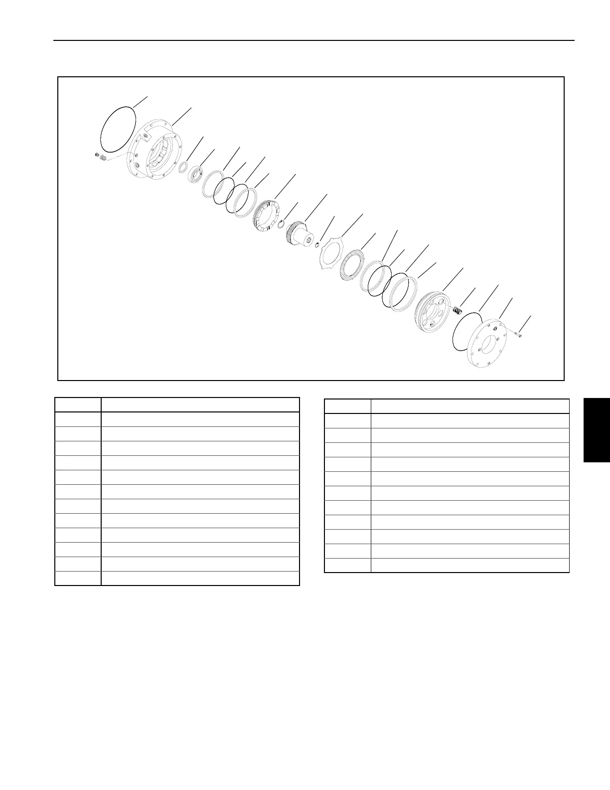
(See Figure 6-3 for reference numbers.)
Assembly is in reverse order of disassembly with the
following additional instructions.
1. Lubricate the sealing lip of the oil seal (4) with the same
type of hydraulic oil that the crane uses. Press the oil
seal into the brake housing (3) with the open side of the
seal facing the hydraulic motor end of the brake
assembly. Install the bearing (5) into the brake housing.
2. If replacing the dynamic brake o-rings (7 and 8), be sure
to install the o-rings and their backup rings (6 and 9) in
the same order in which they were removed. Lubricate
with hydraulic oil to aid assembly.
FIGURE 6-3
1
3
4
5
6
7
8
9
10
11
12
13
14
15
16
17
18
19
20
21
22
23
24
Item Component
1O-ring
3 Housing
4 Seal
5 Bearing
6 Backup Ring
7O-ring
8O-ring
9 Backup Ring
10 Brake Piston
11 Retaining Ring
12 Brake Driver
13 Retaining Ring
14 Stator Plates
15 Friction Discs
16 Backup Ring
17 O-ring
18 O-ring
19 Backup Ring
20 Park Brake Piston
21 Springs
22 O-ring
23 Cover
24 Capscrews (8)
Item Component

 Loading...


