OUTRIGGERS 1300A
7-2 01-22-2019 Control # 051-08
Removal
1. Check that the stabilizer (1) is fully retracted and the
float removed.
2. On the stabilizer end of the beam, remove the side wear
pad set screw in the outrigger box and back off the side
wear pad (2) See figure Figure 7-6.
3. Extend the outrigger beam (10) slightly so that a lifting
strap (Figure 7-2) can be attached to the outrigger
beam.
NOTE: To prevent nick and gouges to the bottom of the
outrigger beam, do not attach chains to the
outrigger beam.
6
4
9
10
1
7
5
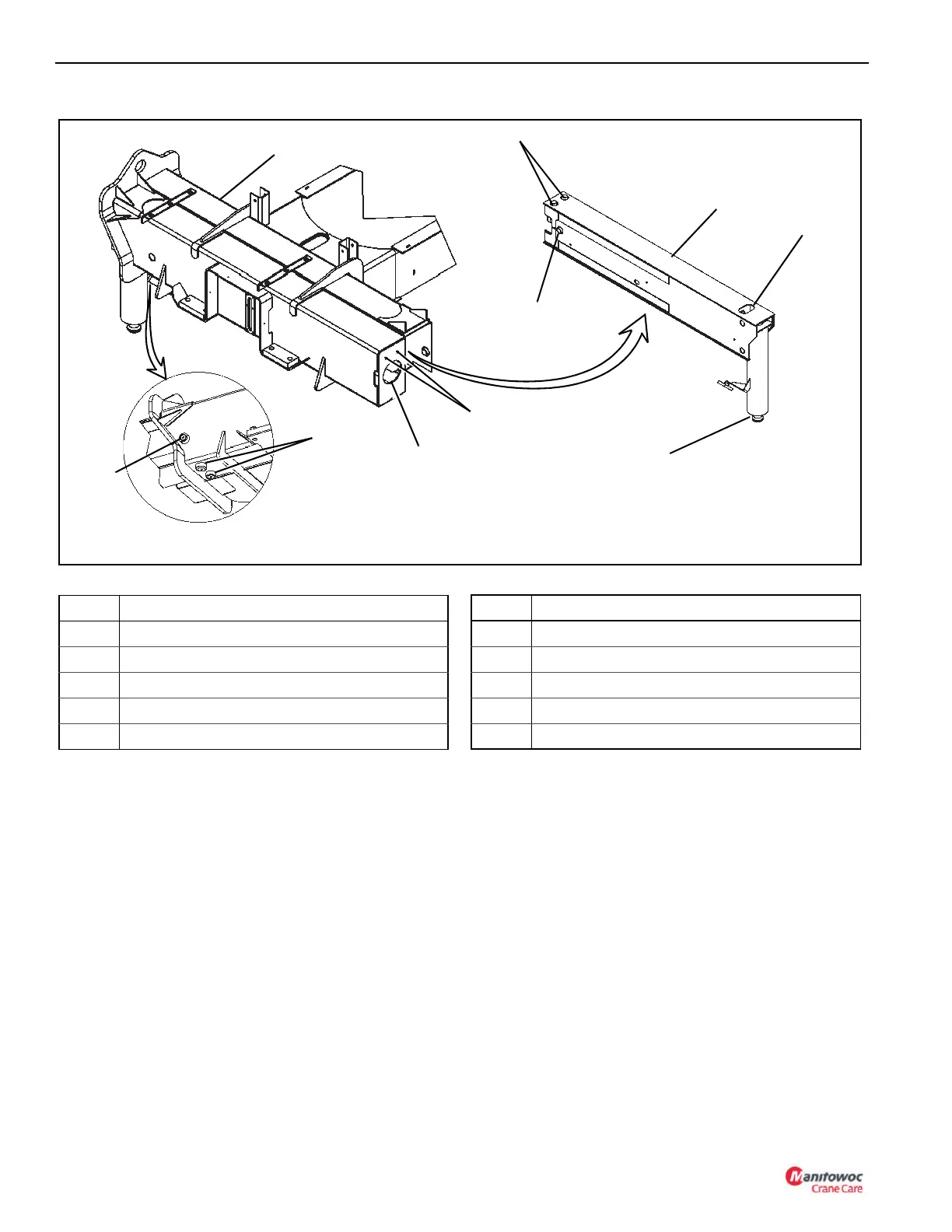
FIGURE 7-1
3
2
8
Item Component
1 Stabilizer
2 Outrigger Box Side Wear Pad (One Side)
3 Outrigger Box Bottom Wear Pads
4 Outrigger Box
5 Access Hole (Outrigger Box)
6 Extension Cylinder Bolts
7 Outrigger Beam Top Wear Pads
8 Outrigger Beam Side Wear Pad (Both Sides)
9 Outrigger Beam
10 Access Hole (Outrigger Beam)
Item Component

 Loading...


