HYDRAULIC SYSTEM 1300A
2-14 01-22-2019 Control # 051-08
SUPPLY PRESSURE AND RETURN CIRCUIT
Description
The supply pressure and return circuit routes hydraulic oil
from the hydraulic pumps to the directional control valve for
the individual operating circuits. The supply pressure and
return circuit consists of the reservoir and integral filter,
hydraulic gear pumps, a hydraulic oil cooler, and a 6-port
hydraulic swivel.
Swivel ports 2, 3, and 4 are used to supply pressure to all
crane function and hydraulic controller circuit. Swivel port 5
is used for the return circuit that is routed through the
hydraulic filter in the hydraulic tank. Swivel port 6 is for the
HRC return and is not routed through the hydraulic filter.
Hydraulic Reservoir, Filter, and Oil Cooler
The reservoir, (Figure 2-10) is attached to the front of the
truck bed and has a capacity of 76 U.S. gallons (287 liters) to
the full mark. The all-steel reservoir has an internally
mounted full flow filter and integral baffles that help cool the
hydraulic oil and prevent foaming.
Hydraulic oil flows through the suction line at the lower front
of the reservoir to the hydraulic pump. Most of the return flow
goes through the filter at the top of the reservoir. The return
line that goes directly into the reservoir (instead of through
the filter) is from the swivel port 6 (drain) of the 6-port swivel
and the outrigger return line.
A magnetized drain plug in the bottom of the reservoir
collects metal particles from the hydraulic oil if it becomes
contaminated.
A sight gauge is located on the side of the reservoir to
indicate hydraulic oil level.
A filler cap on the top of the reservoir is for filling the
reservoir. The filler cap includes a strainer for catching
contaminants and gaskets to prevent leaking. A breather cap
(vent) which is part of the filler cap allows air to enter or leave
the reservoir. The breather must be kept clean to prevent
damage to the reservoir.
A large access cover on the top of the reservoir provides
access for cleaning. The cover is secured to the top of the
reservoir with screws and has a gasket to prevent leaking.
The access hole can also be used to fill the reservoir after it
has been completely drained.
The hydraulic oil filter (Figure 2-10) is located in the reservoir
and bolts to the top of the reservoir. The filter housing
contains a replaceable filter element.
A filter element gauge on the filter head indicates how
restricted (clogged) the filter element is. When back pressure
caused by a dirty filter element exceeds 15 psi (103 kPa), the
filter head’s bypass feature allows the hydraulic oil to bypass
the filter and flow into the reservoir.
S
F
O
B
o
t
t
o
m
S
F
O
T
o
p
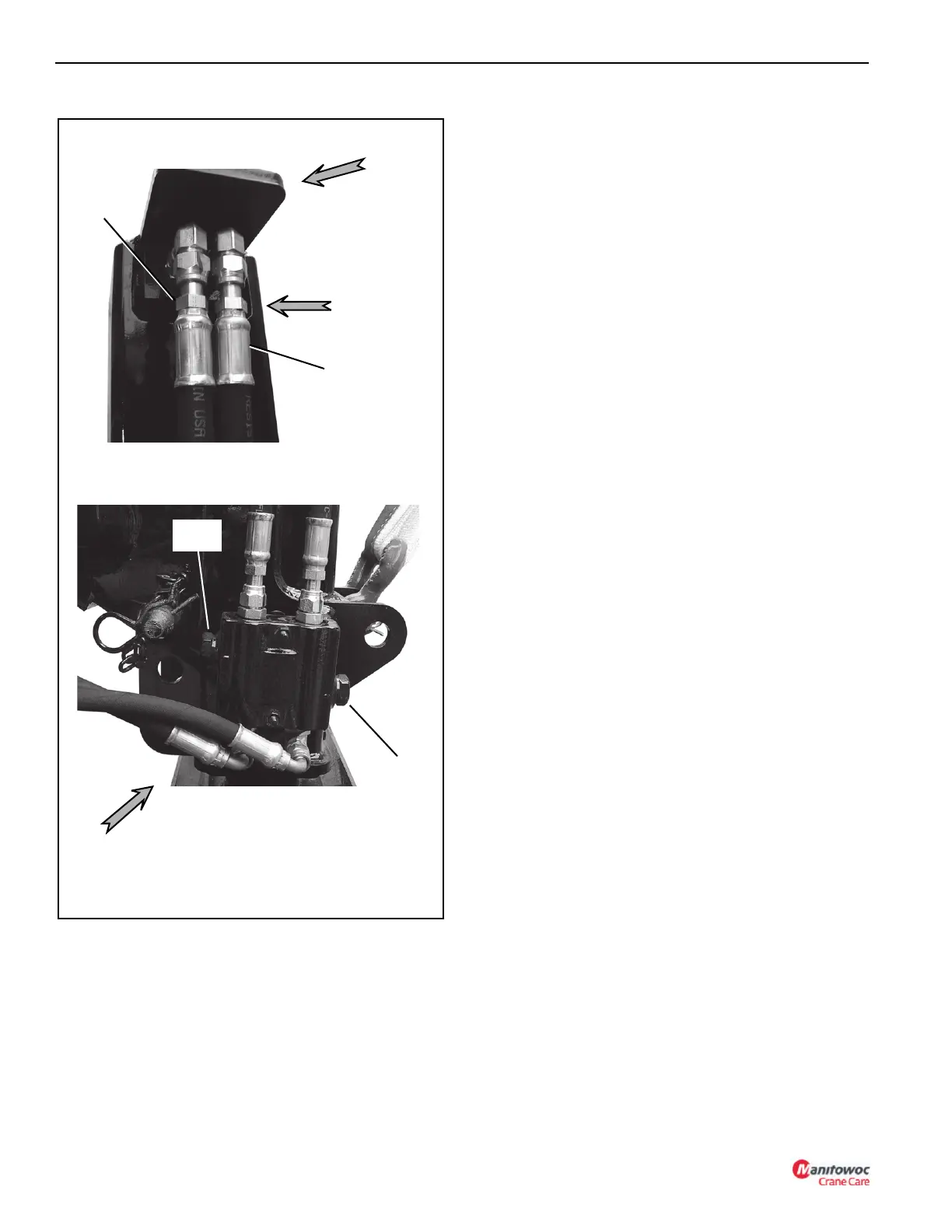
Extend Line
Retract
Line
Retract
Relief
FIGURE 2-9
Front
Extend
Relief

 Loading...


