HYDRAULIC SYSTEM 1300A
2-18 01-22-2019 Control # 051-08
Installation
1. Lubricate the splines on the pump and PTO drive shaft
coupling with heavy lithium grease.
2. Line up the splines on the PTO drive shaft coupling up
with the pump drive shaft and slide the pump drive shaft
into the coupling.
3. Bolt the pump to the PTO with the pump mounting
flange.
4. Bolt the pump rear mounting bracket to the truck
mounting bracket.
5. Reconnect the hydraulic lines as per removal tags.
6. Fill the hydraulic tank to the full mark with hydraulic oil.
7. Start the truck engine at idle and engage the PTO.
8. Let the truck idle until the system is pressurized to make
sure that the hydraulic oil has replenished the system
and that the system is not sucking air.
9. Shut the truck engine in the cab off and restart from the
crane cab.
10. Check all crane functions.
Initial Pump Installation
For initial pump installation, use the following procedure:
1. The hydraulic gear pump has integral mounting flanges
and can be bolted directly to the PTO. Be sure adequate
clearance exists for this type of pump mount.
2. If the pump is powered through a drive line, a pump
mount must be installed or bolt the pump to an existing
frame cross member.
3. A mounting bracket needs to be installed so that the rear
mounting bracket on the pump can be secured.
4. Be sure the drive line is sized to safely carry the
maximum pump horsepower requirements (189 hp
(140.9 kw) at 1800 rpm).
5. Do not locate the pump more than 42 inches (107 cm)
from the PTO. Do not exceed a 7° drive line angle and
the U-joints on both ends of the drive shaft must be
parallel with each other.
6. Plan the location of the pump mount and drive line for
adaquate clearance between the pump and truck drive
shaft or exhaust system.
7. Position the pump so that hydraulic lines can be
connected without sharp bends especially the large
suction line from the reservoir.
8. For drive line installation, install the pump mount to the
truck frame.
9. Lubricate the splines on the pump shaft and drive
coupling with heavy lithium grease.
10. Bolt the pump mounting flange to the PTO or to the
pump mount on the truck.
11. Torque the mounting flange nuts to 50 ft. lbs (222N
.
m).
12. Bolt the pump rear mounting bracket to the truck
mounting bracket.
NOTE: O-ring boss fittings are used for sealing hydraulic
line connections. Make sure the O-ring is in its
grove before tightening.
13. Remove the dust covers from the pump inlet and outlet
ports and install the hydraulic fittings and lines.
14. Fill the reservoir with the proper hydraulic fluid to the
high-level mark on the reservoir sight gage.
15. Start the engine, run at idle a few minutes, and check for
leaks.
16. Increase engine speed to governed rpm for 1-2 minutes
and check for leaks.
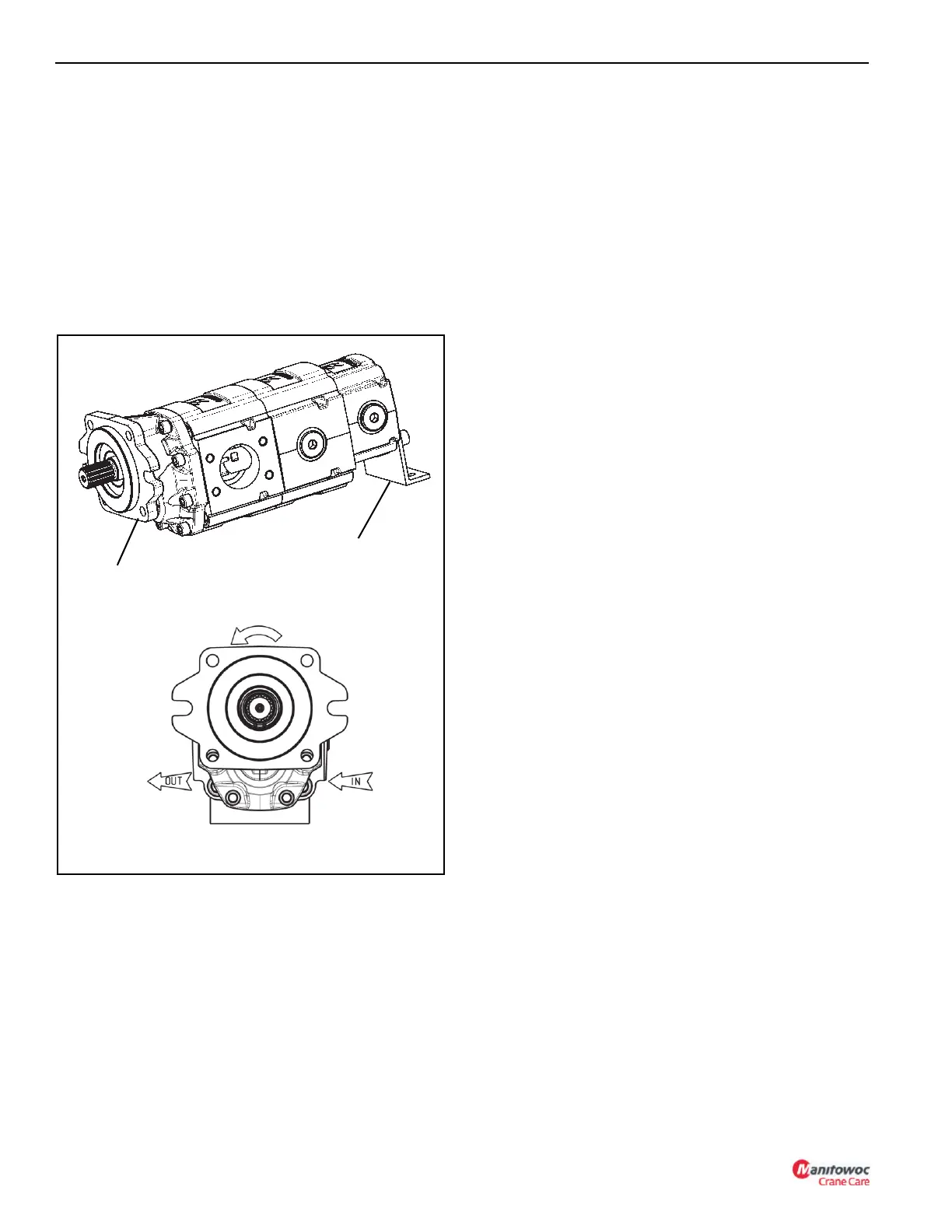
Pump Mounting
Flange
Rear Pump
Mounting Bracket
FIGURE 2- 12
CCW Rotation

 Loading...


