National Crane 01-22-2019 Control # 051-08 3-5
1300A ELECTRIC SYSTEM
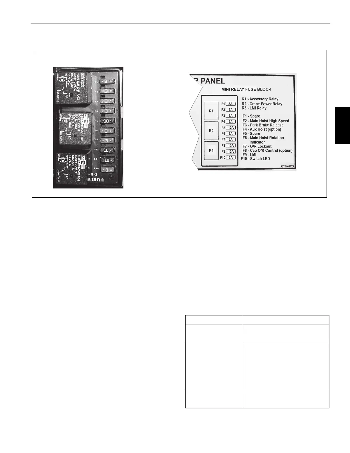
Mini Relay Fuse Block
The mini relay fuse block is located on the right and contains
the following components:
• R1 — Accessory relay supplies power to micro fuse
block F1 through F10 when energized by the crane
ignition switch.
• R2 — Crane power relay supplies power to mini fuse
block F1 through F10 when energized by the crane
power switch.
• R3 — Supplies power to the RCL lockout solenoids
when not at capacity, not two-blocked, or when
overridden.
• F1 — Spare
• F2 — Main hoist burst of speed circuit.
• F3 — Park Brake Release circuit for the swing brake
switch on the crane cab console.
• F4 — Auxiliary hoist circuit (optional).
• F5 — Not used
• F6 — Main hoist rotation indicator circuit.
• F7 — Outrigger Lockout circuit disables the outriggers
when the crane function power switch is on.
• F8 — Cab Outrigger circuit for outrigger control from the
crane cab (optional).
• F9 — RCL lockout solenoids circuit.
• F10 — Switch LED’s on the crane cab console.
Horn Alarm Circuit
The horn alarm sounds in the following conditions:
• The operator depresses the horn switch on the front
console.
• The operator leaves the operator’s seat without turning
off the crane function power switch.
• The operator depresses the horn switch in the left
armrest.
Mini Relay Fuse Block
FIGURE 3-3
Fault Check
Horn switch does not
activate horn
• Fuse F2 in micro fuse block
• Horn switch
Seat safety switch
does not activate horn
• Fuse holder in crane cab
console (Figure 3-1 Item 5)
• Horn relay R4 in micro fuse
block
• horn alarm relay R3 in micro
fuse block
Armrest horn switch
does not activate horn
• Fuse F2 in micro fuse block
• Horn switch

 Loading...


