National Crane 01-22-2019 Control # 051-08 5-3
1300A HOIST
Hydraulic Hoses
1. Inspect the hydraulic hoses and replace as required.
2. Inspect the anti-chafing sleeve and replace as required.
3. Route replaced hydraulic hoses through the anti-chafing
sleeve.
Hoist Installation
1. Remove the rope mesh guard from hoist and attach a
lifting device to the hoist.
2. Lift the hoist with a lifting device onto the back of the
boom.
3. Align the alignment slots on the hoist with the alignment
ears on the boom and lower hoist onto the boom.
4. Install mounting bolts and washers.
5. Remove the lifting device.
6. Install the mesh guard and secure with the U-bolts.
7. Reinstall the hydraulic hoses as per removal tags.
DRUM ROTATION INDICATOR
The Drum Rotation Indicator (DRI) and Minimum Wrap
Indicator (MWI) are integrated into one Hoist Monitoring
System (HMS) located on the left side of the hoist and
transmits a rotation signal to a solenoid (thumb thumper)
located in the hoist control lever on the operator’s seat.
The DRI transducer and integral Minimum Wrap Indicator
(MWI) is programmed to notify the operator when there are
three wraps of wire or synthetic rope remaining on the hoist
drum.
The HMS is available with two systems, Series, “A” and
Series “B”. The HMS is available with a CAN J1939, (Series
“B”), allowing the device to interface with the Rated Capacity
Limiter (RCL) system.
Series “A” units can be distinguished by a single cable
connection on the HMS, located on the left side of the hoist.
Series “B” units have a second connection (CAN J1939)
along with an integrated protection circuitry, acting as a
circuit breaker, on the MWI and DRI (Thumper) outputs.
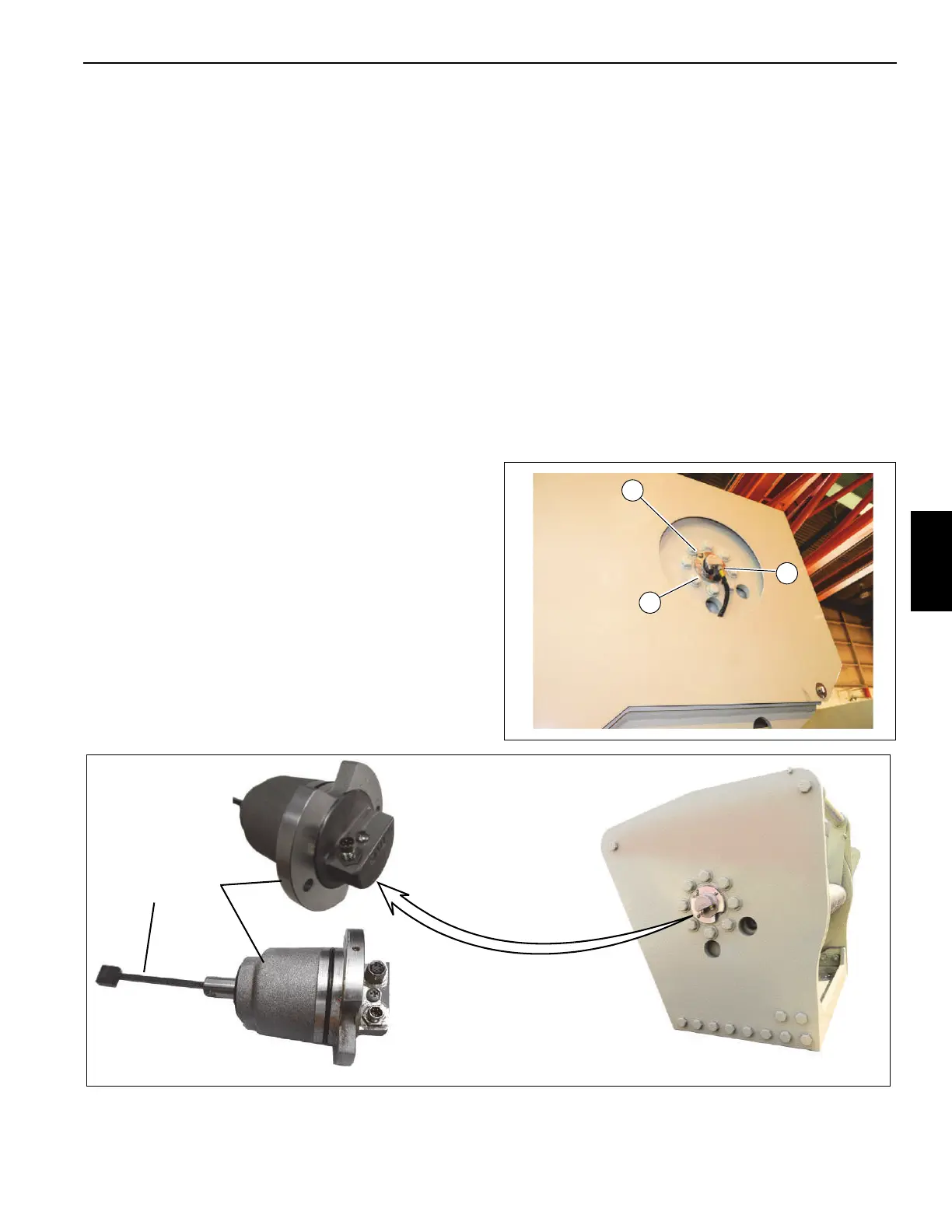
Removal
1. Loosen the collar on the connector and unplug the DRI
cable (1, Figure 5-2).
2. Remove the two retaining screws (2).
3. Remove the DRI unit from the hoist.
4. Loosen set screw and remove shaft assembly from
MWI.
FIGURE 5-3
2
1
8640-1
8640-8
Series A
Series B
8640-2

 Loading...


