National Crane 01-22-2019 Control # 051-08 9-17
1300A CRANE INSTALLATION
Bolt On (Standard)
Make sure the truck has been configured to meet the
minimum truck, PTO, and frame strength requirements as
described on 1 through 15. Mounting the crane to the truck
frame is as follows:
1. Place the crane assembly on the truck frame as
determined by the information contained in the section
titled Positioning the Crane On the Truck on 10.
2. Locate the upper mounting plates (4 places) on the
T-box frame as shown in Figure 9-13 and weld on four
sides.
3. Bolt the anchor bar (Figure 9-11) to the upper mounting
plate finger tight.
4. Bolt the lower anchor mounting to the anchor bar finger
tight.
5. Drill four bolt holes through the truck frame using the
lower mounting plate to locate the bolt holes.
6. Cut the cross bar to fit (Figure 9-12) inside the truck
frame with the end plate
7. Weld the end plate to the cross bar.
8. Clamp the cross bar in place and drill four bolt holes
using the Lower Mounting Plate to locate the bolt holes.
9. Install the through the lower mounting plate and cross
bar end plate (Figure 9-12.
10. Tighten all mounting bolts.
11. Locate the doubler Figure 9-13 and weld on all sides.
12. Locate the rear mounting plate on the T-box frame and
weld on three sides.
13. Drill four holes through the lower mounting plate and the
truck frame.
14. Install and tighten the four bolts in the lower mounting
plate.
DANGER
It is mandatory that swing bearing and T-box attaching
bolts be inspected and re-torqued after the first 300 hours
of crane operation and every 500 hours thereafter. The
bolts may loosen and cause the crane to separate from
the carrier which will result in damage to the crane and
possible injury or death to personnel.
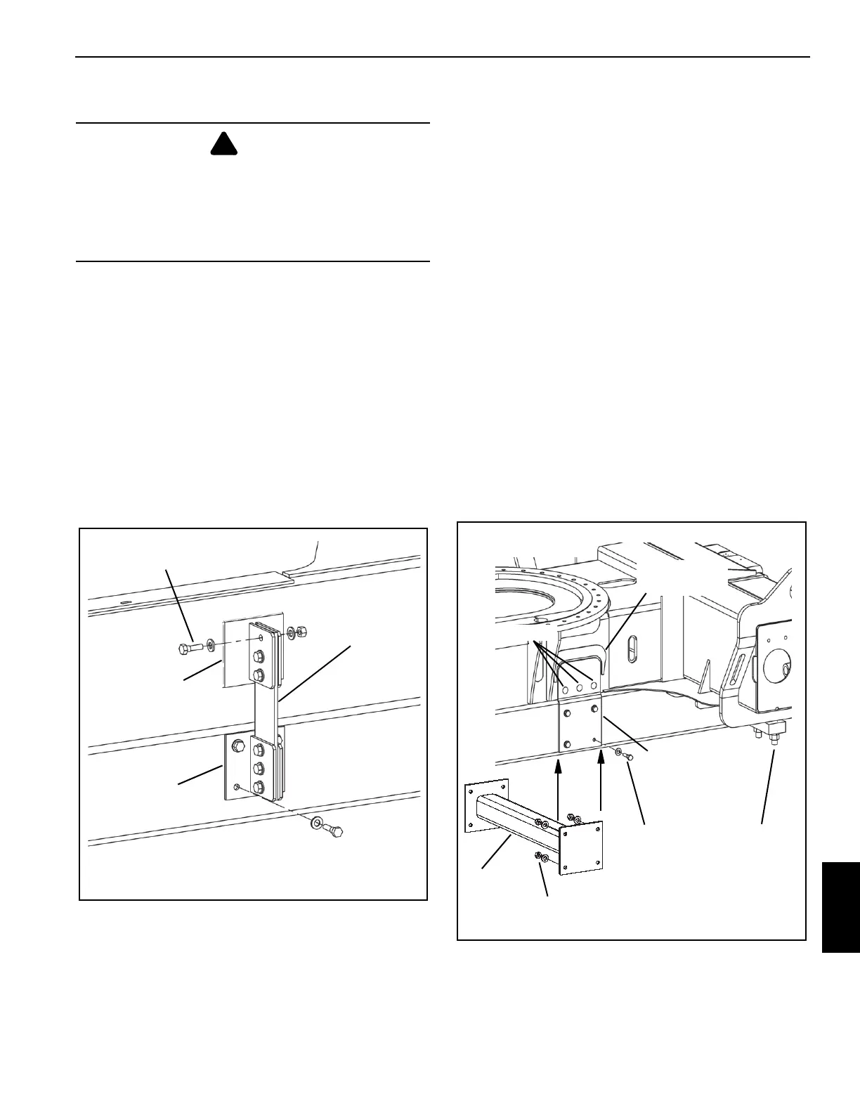
Upper Mounting
Plate Welded To
T-box Frame.
Anchor Bar
Lower Mounting
Plate Bolted To
Truck Frame.
FIGURE 9-11
5/8 UNC Grade 8 Bolt
FIGURE 9-12
Weld 3 Spots
Doubler (weld all
sides)
Rear
Clamp
Cross
Bar
5/8 UNC Grade
8 Nut
5/8 UNC
Grade 8 Bolt
Rear Mounting Plate,
Weld to T-Box Frame,
Bolt to Truck Frame
NOTE: All welds must be
grade 70 or better.

 Loading...


