National Crane 01-22-2019 Control # 051-08 2-7
1300A HYDRAULIC SYSTEM
Hydraulic circuit routing is as follows:
• The hoist circuit is routed from pump section one (P1)
through swivel port three to the directional control valve
and on to the hoist motor.
• The lift and telescope circuit is routed from pump section
two (P2) through swivel port four and to the directional
control valve and onto the lift and telescope cylinders.
• The swing circuit is routed from pump section three (P3)
though the front outrigger manifold, the hydraulic swivel,
the crane manifold, the directional control valve, and
onto the swing motor.
VALVES
General
This subsection provides descriptive information for all the
hydraulic valves used on this crane. For a listing of all valves,
the circuit they are used in, and their physical location, refer
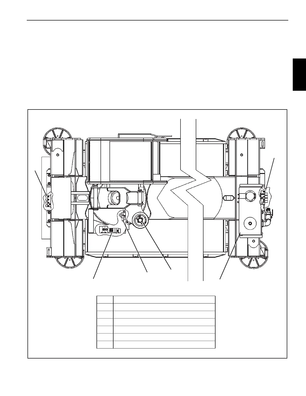
to the table on 8. Refer to (Figure 2-2) for valve locations.
The description of each valve given here is for the valve
itself. For information on how each valve functions in the
individual circuits, refer to the description and operation
procedures of that circuit.
Item Component
1 Rear Outrigger Manifold
2 Main Control Valve (lift, telescope, hoist, swing)
3 Crane Manifold
4 Swing Motor and Manifold
5 Hydraulic Reservoir
6 Single Front Outrigger Manifold
1
2
3
5
6
FIGURE 2-2
4

 Loading...


