HYDRAULIC SYSTEM 1300A
2-6 01-22-2019 Control # 051-08
• To remove entrapped air from telescope cylinders, lower
the boom to below horizontal and fully telescope the
boom in and out several times.
• If the air is not readily removed, lower the boom to below
horizontal, extend the telescope cylinders as far as
practicable, and allow the boom to remain in this position
overnight. This should allow entrapped air to find its way
to the holding valve so that telescoping the boom IN the
next morning should force the air back to the reservoir.
Ensure the boom is first telescoped IN (not OUT) in the
morning. Telescoping OUT may cause air to be forced
back into the cylinder.
• Entrapped air may be removed from cylinders having
wet rods by cycling. On certain cylinders, a plugged port
is provided on the rod end to bleed off entrapped air.
• In the event that air entrapment should persist, bleeding
of air by loosening various clamp and screw type fittings
may become necessary.
• If the above procedures fail to eliminate air entrapment,
contact your authorized National Crane distributor.
Parts Replacement
Parts found damaged or out of tolerance when maintenance
is being performed should be replaced. Refer to the Grove
Parts Catalog for proper replacement parts.
Maintenance Records
Dated records must be kept for inspection of critical
components such as, brakes, crane hooks, wire ropes,
hydraulic cylinders and relief valve pressure settings. These
records must be kept where they can be easily obtained and
reviewed.
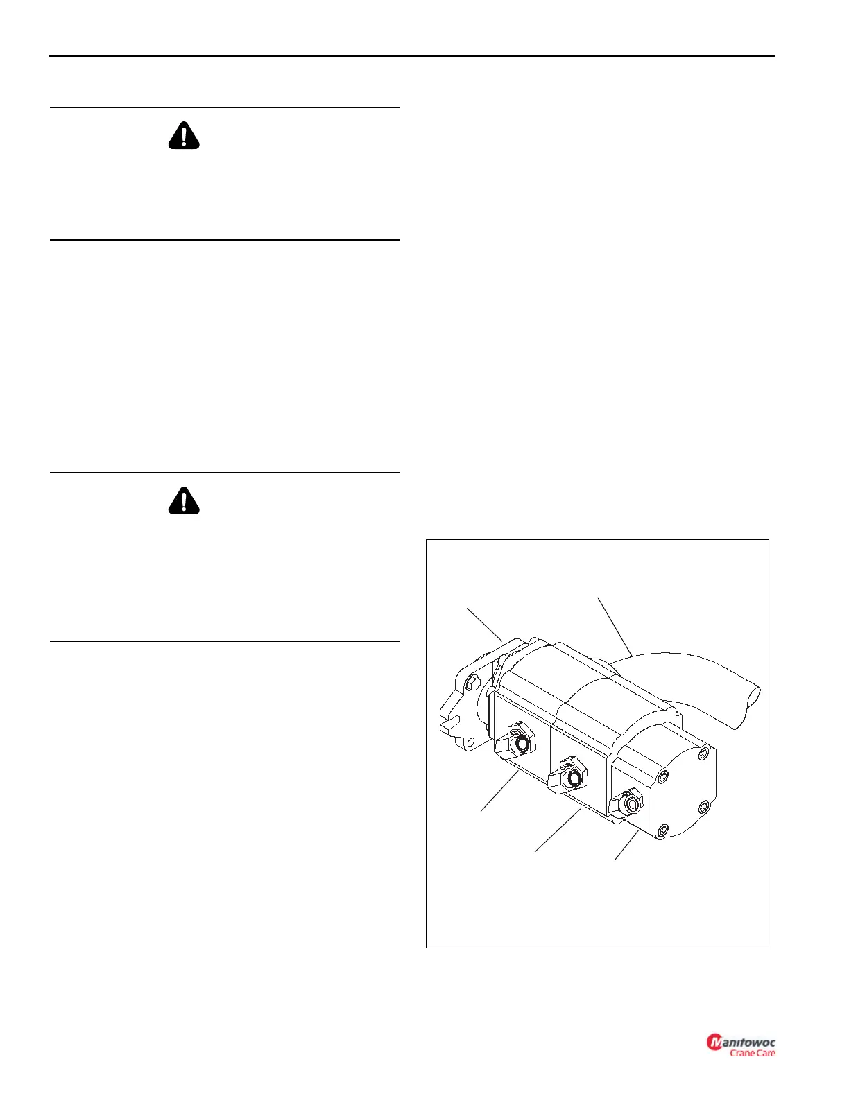
HYDRAULIC PUMP
The hydraulic system pressure is supplied by a three section
hydraulic gear pump mounted on the truck power take off
(PTO). Hydraulic system operating temperature is from
-20°F to +200° F (-28.8°C to 93.3° C). The pump is driven
counter clockwise and supplies the following at 1800 rpm:
• P1 supplies 34 gpm (128.7 lpm) at 3300 psi (227.5 bar)
for the hoist circuit.
• P2 supplies 29 gpm (109.7 lpm) at 3600 psi (248.2 bar)
for the telescope and lift circuits.
• P3 supplies (52.9 lpm) 3000 psi (206.8 bar) at 14 gpm
for the outrigger circuit and 12 gpm for the swing circuit.
A directional control valve mounted in the enclosure on the
turret controls direction of the swing, hoist, lift, and telescope
circuits.
A flow divider located in the crane manifold mounted in the
enclosure on the turret provides pilot pressure for the
controllers, swing brake release pressure, and burst of
speed flow.
CAUTION
Always locate the machine on a firm supporting surface,
extend the outriggers and level the machine and position
the boom over the front to extend the boom at low angles.
Injury or damage to the machine may result if this caution
is not followed.
CAUTION
Do not attempt to loosen fittings in pressurized lines or
while the hydraulic pumps are in operation.
Extreme care must be used when removing any plugs or
restrictions from a hydraulic system suspected to have
entrapped air that may be pressurized. Moderate to minor
injury may result from pressurized air in a hydraulic
system.
Section P1
Section P2
Section P3
Suction Supply
3 Section
Gear Pump
FIGURE 2-1

 Loading...


