BOOM MAINTENANCE 1300A
4-10 01-22-2019 Control # 051-08
6. Install the telescope cylinder the rest of the way into the
boom assembly.
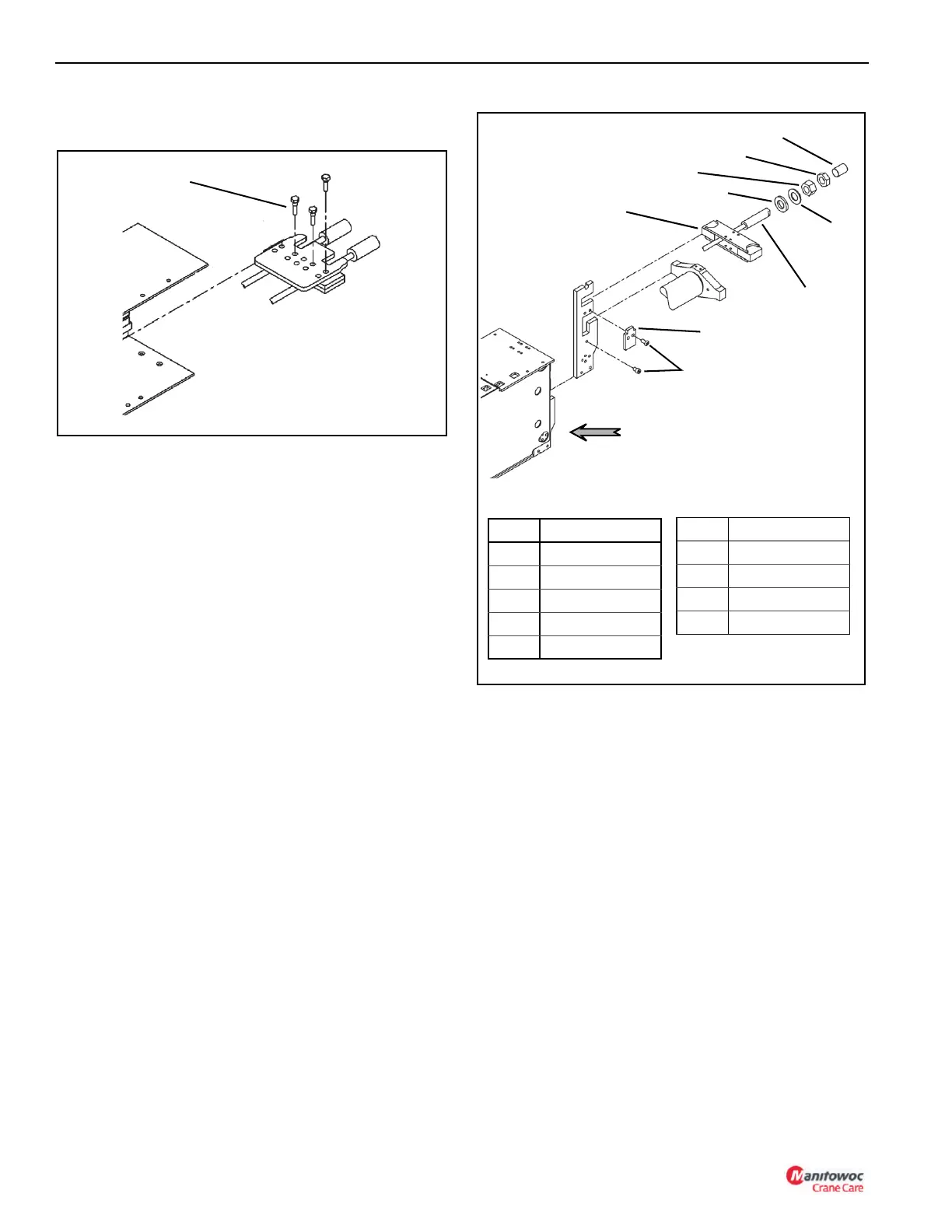
7. Insert the extend cable anchor assembly into the base
end of the 2
nd
section (Figure 4-17).
8. Thread the extend cable through the extend cable
anchor assembly.
9. Install the following onto the extend cable in the
following order:
a. Spacer
b. Round washer
c. Hex nut
d. Jam nut
e. Cable protector
f. Retainer plate
g. Two cap screws
2
nd
, 3
rd
, 4
th
BOOM SECTION INSTALLATION
1. Slide the 2
nd
, 3
rd
, 4
th
, section assemblies into the 1
st
section until 4 to 5 feet of the assembly is left.
2. Install the lower wear pads at the front end of the 1
st
section and secure with cap screws (Figure 4-18).
3. Install the side wear pads and shims as required. Secure
with cap screws
4. Install the upper wear pad and secure with a flat washer
and cap screws.
FIGURE 4-17
Item Component
1 Cable Protector
2Jam Nut
3Hex Nut
4 Flat Washer
5 Anchor Assembly
6 Cap Screw
7 Retainer Plate
8 Extend Cable
9Spacer
Item Component
1
2
3
4
5
6
7
8
9
Base End of 2
nd
Section

 Loading...


