ELECTRIC SYSTEM 1300A
3-4 01-22-2019 Control # 051-08
INDIVIDUAL FUSE HOLDERS
There are several fuses contained in individual fuse holders
located in the crane cab console (Figure 3-1). These are:
• Crane cab heater circuit fuse (1) (20A).
• Crane power fuse (2) (30A) in line circuit to both the
micro and mini fuse block circuits.
• Seat safety switch circuit fuse (5) (3A).
• Crane cab accessory circuit fuse (3) (20A).
The side panel (13) may need to be removed to gain access
to the individual fuse holders.
RELAY FUSE BLOCKS
There are two relay/fuse blocks located in fuse compartment
(Figure 3-1) in the crane cab console. Loosen the two
thumbscrews and remove the access panel located on the
side of the crane cab console to gain access to the fuse
block. A decal on the inside of the access panel identifies the
relay and fuse circuits.
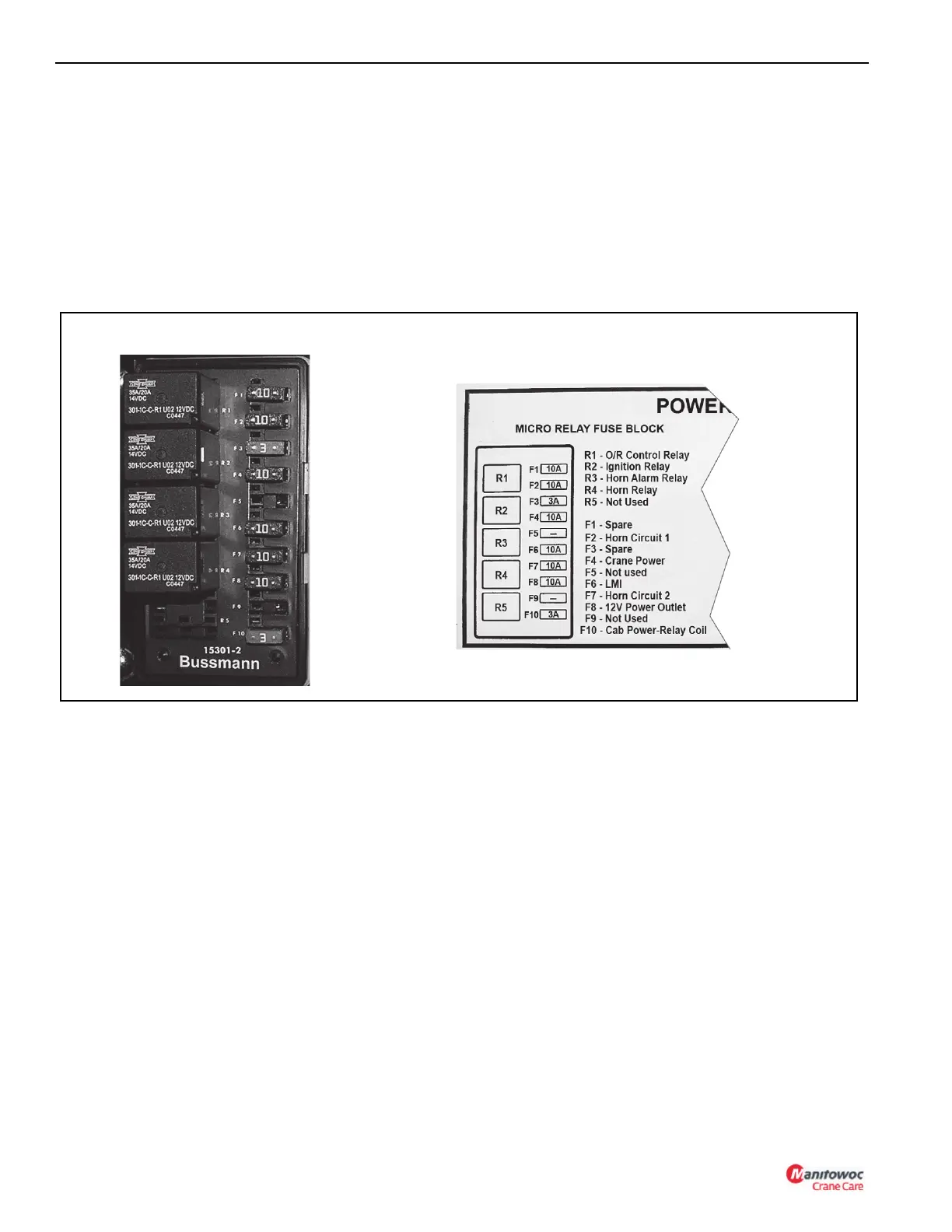
Micro Relay Fuse Block
The micro relay fuse block (Figure 3-2) is located on the left
side of the fuse compartment and contains the following
components:
• R1 - Outrigger Control Relay disables the outrigger
controls when energized by the radio remote switch.
• R2 - Ignition Relay disables the crane and truck cab
ignition switches and transfers the start function to the
radio remote when energized by the radio remote
switch.
• R3 - Horn Alarm Relay enables the horn when energized
by the operator’s seat safety switch.
• R4 - Horn Relay supplies power for the horn alarm. R4 is
energized by relay R3 or by the armrest safety switch or
crane cab console horn switch.
• R5 - Not used
• F1 - Spare
• F2 - Horn Circuit 1 supplies power to the horn relay R4
when armrest safety switch is closed or to the horn when
the horn switch on the crane cab console is closed.
• F3 - Spare
• F4 - Crane Power Function supplies power to the crane
power relay when the crane power switch is energized.
• F5 - Not used
• F6 - RCL power.
• F7 - Horn Circuit 2 supplies power for the horn alarm
when horn relay R4 is energized.
• F8 - 12V Power Outlet supplies power to the 12V power
outlet on the crane cab console.
• F9 - Not used.
• F10 - Crane Cab Power-Relay Coil supplies power to
the crane cab power relay for crane cab accessory
power.
Micro Relay Fuse Block
FIGURE 3-2

 Loading...


