ELECTRIC SYSTEM 1300A
3-8 01-22-2019 Control # 051-08
OUTRIGGER MANIFOLDS
There are two outrigger manifolds located on the carrier
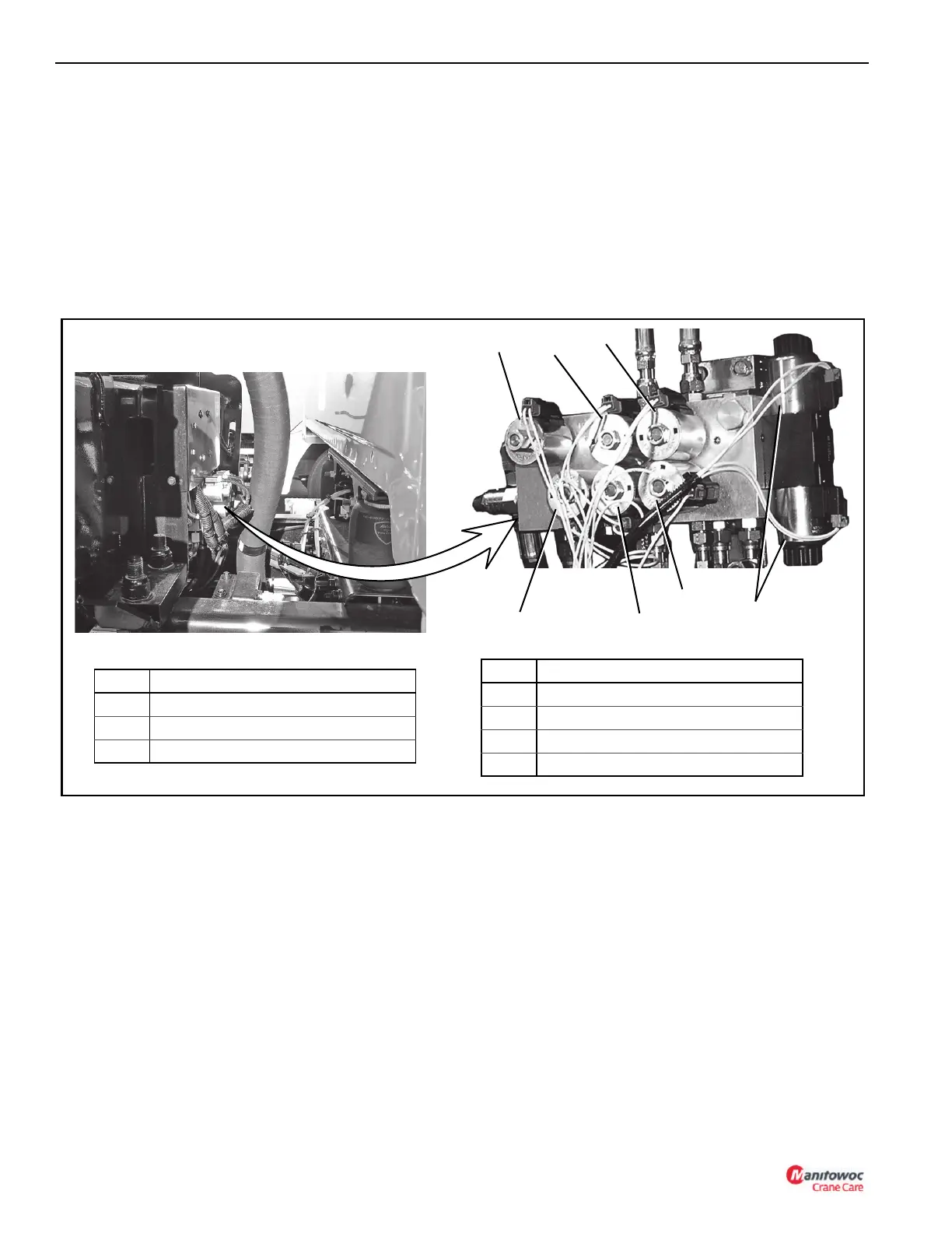
frame. The front outrigger manifold is mounted on the center
of the front outrigger box (Figure 3-6) and the rear outrigger
manifold is mounted in an enclosure on the back of the rear
outrigger box (Figure 3-7).
The swing and outrigger functions are on the same hydraulic
circuit however, only one function at a time can be working.
Selection of the function is determined by the outrigger
enable valve which directs the flow to either the swing or
outrigger circuit. When the outrigger control valve is
energized by the extend\retract switch, all flow is directed to
the outrigger circuit.
Front Outrigger Manifold
The solenoids on the front outrigger manifold control the
selection of the front outrigger components, front center jack,
the extend and retract functions of all outrigger components,
and the hydraulic flow to the outrigger hydraulic circuit.
.
The solenoids on the front outrigger manifold provide the
following functions:
NOTE: When the crane function power switch in the crane
cab console is turned ON, all outrigger functions
are disabled.
• The outrigger enable solenoid (1) diverts all flow in the
outrigger/swing circuit to the outriggers when energized.
When the solenoid is not energized, all flow is directed to
the swing circuit.
NOTE: The outrigger enable and extend/retract solenoids
are energized at the same time by the extend/
retract switch on the outrigger control box.
• The single front outrigger (2) solenoid extends or
retracts the SFO when energized. Any time the retract
switch on the outrigger control is depressed, the SFO is
first up.
• The extend/retract solenoid (7) controls the extend and
retract functions for all outrigger components.
• The component solenoids (3 through 6) control the front
outrigger components. See Figure 3-6 for solenoid
identification.
Rear Outrigger Manifold
The solenoids on the rear outrigger manifold (1 through 4)
control the rear outrigger components. See Figure 3-7 for
solenoid identification.
1
FIGURE 3-6
Item Solenoid
1 Outrigger Enable
2 Single Front Outrigger (SFO) (Optional)
3 Passenger Side Stabilizer
5
6
7
4
3
2
4 Passenger Side Beam
5 Driver Side Beam
6 Driver Side Stabilizer
7 Extend/Retract
Item Solenoid

 Loading...


