National Crane 01-22-2019 Control # 051-08 5-5
1300A HOIST
Shipping Mode (Series A Only)
If the programming button is held down for more than 15
seconds, the HMS will enter "Shipping Mode (Series A
Only)." The HMS rapidly pulses the "Warning" output
indicating the HMS is entering or exiting "Shipping Mode."
While in "Shipping Mode", the HMS will pulse the "Warning"
output two times with a 30 second pause.
Shipping Mode allows the OEM to set the set points on the
cable before shipping to a job site. This prevents the need to
recalibrate the set points when the winch is installed on the
machine.
NOTE: The drum rotation indication, commonly a thumper
handle, remains operational while the HMS is in
shipping mode.
To use Shipping Mode:
1. Install the wire rope on the drum. Refer to the
appropriate winch manual for more information.
2. See See “Programming the Minimum Wrap Indicator” on
page 5-4 to set the end points.
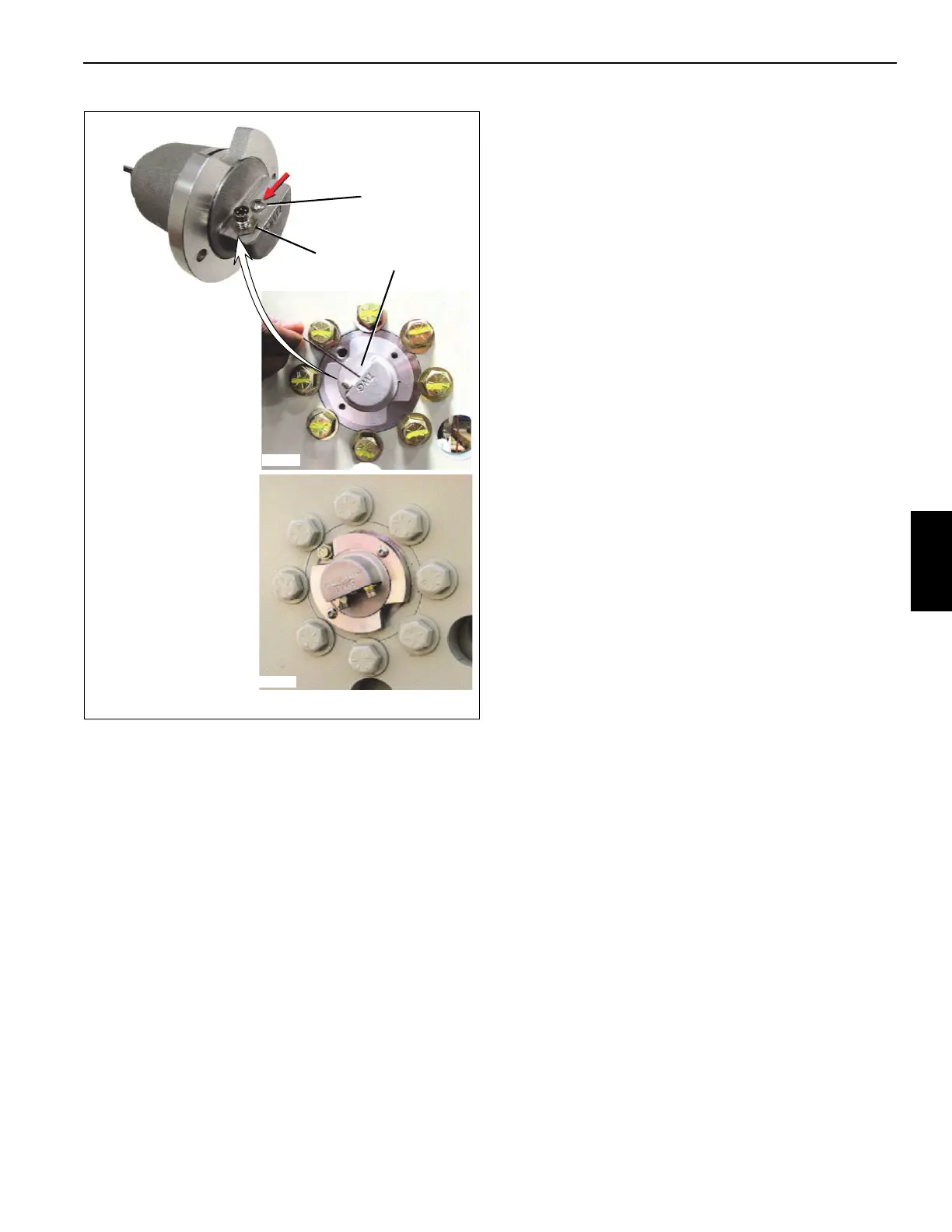
3. Remove the programming button cover screw (1,
Figure 5-5).
4. Press and gently hold the programming button for at
least 15 seconds. The HMS rapidly pulses the “Warning”
output to confirm the HMS has entered Shipping Mode.
The set points remain saved in the HMS
.
NOTE: Excess force can damage the programming button
and affect MWI/HMS operation.
5. This allows the winch to rotate without the count or set
points being disturbed.
6. When the winch is installed on the machine and the wire
rope is installed to the same length as the original setup,
press and hold the programming button for more than 15
seconds. The HMS rapidly pulses the "Warning" output
to confirm the HMS is no longer in Shipping Mode.
7. The HMS is now ready for use.
TROUBLESHOOTING
For Series “A”
Check the in-line fuse used to protect the thumper line.
Series “B” Circuit Breaker Reset
Instructions
Series “B”, units have integrated protection circuitry, acting
as a circuit breaker on MWI and DRI outputs. If circuit
breaker trips, remove power (turn OFF key switch or
disconnect cable) and inspect load devices, (Thumper
handles).
HOIST REPAIR
Disassembly
The following steps describe how to disassemble the hoist.
Inspect and replace all worn parts.
1. Stand the hoist on its end with the motor pointing up.
Place blocking under the side plate so the hoist is not
sitting on the shaft (Figure 5-6).
NOTE: See Figure 5-7 for item number (#) identification.
2. Remove the brake hose (46) from the straight
adapter (45).
3. Remove the motor and counterbalance assembly from
the hoist by removing two capscrews (47) and two
FIGURE 5-5
2
3
1
8640-5
8640-6
Series A
Series B
8640-7

 Loading...


