National Crane 01-22-2019 Control # 051-08 2-15
1300A HYDRAULIC SYSTEM
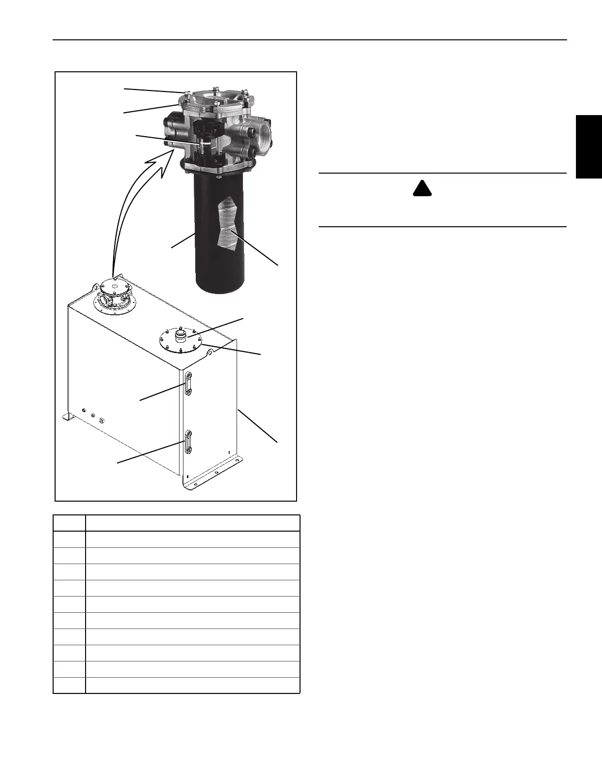
Hydraulic Filter Replacement
The filter is mounted in the oil reservoir, and is a replaceable
element type.
The filter must be serviced with National Crane replacement
elements at recommended intervals to assure the warranty
remains in effect.
Element Removal
1. Shut down the hydraulic system.
2. Wipe any dirt from the filter head and cap assembly.
3. Loosen the six bolts securing the filter cap to the filter
head.
4. Twist to unlock and remove the filter cap.
5. Remove the filter element from the filter bowl (housing).
6. Ensure the new filter element is correct by comparing
their part numbers with the part numbers of the used
filter element.
7. Discard the used filter element.
Element Installation
1. Install the new element into the filter bowl (housing).
2. Install the filter cap and twist to lock in place.
3. Tighten the six bolts to secure the filter cap.
4. Activate the hydraulic system and check for leaks. Make
repairs as needed.
Hydraulic Oil Cooler
A hydraulic oil cooler (Figure 2-11) is located on the driver
side of the hydraulic reservoir. The oil cooler return circuit is
in parallel with the reservoir return circuit. A 30 psi (206 kPa)
check valve in the cooler line regulates flow through the oil
cooler. When the hydraulic oil is cold, most of the return oil
goes directly to the tank. As the oil warms up and becomes
thinner, more oil goes through the cooler.
NOTE: A temperature sensor located in swivel port (1)
monitors the temperature of the hydraulic oil and
illuminates a light on the crane cab console when
the temperature reaches 190° F (87.7° C).
The oil cooler fan is controlled by a relay in the fan housing.
To access the relay, remove the assess panel on the side of
the housing. A temperature switch located in the cooling core
energizes the fan relay when the oil temperature reaches
140°F (60 °C). See Figure 9-15 for fan installation.
Item Component
1 Hydraulic Reservoir
2 Temperature Gauge
3 Hydraulic Oil Level Gauge
4 Access Cover
5 Fill Cap
6Bowl
7 Filter Element Gauge
8Filter
9 Filter Cap
10 Capscrews (6)
DANGER
Ensure that hydraulic system is shut down and the
pressure is relieved.

 Loading...


