National Crane 01-22-2019 Control # 051-08 4-11
1300A BOOM MAINTENANCE
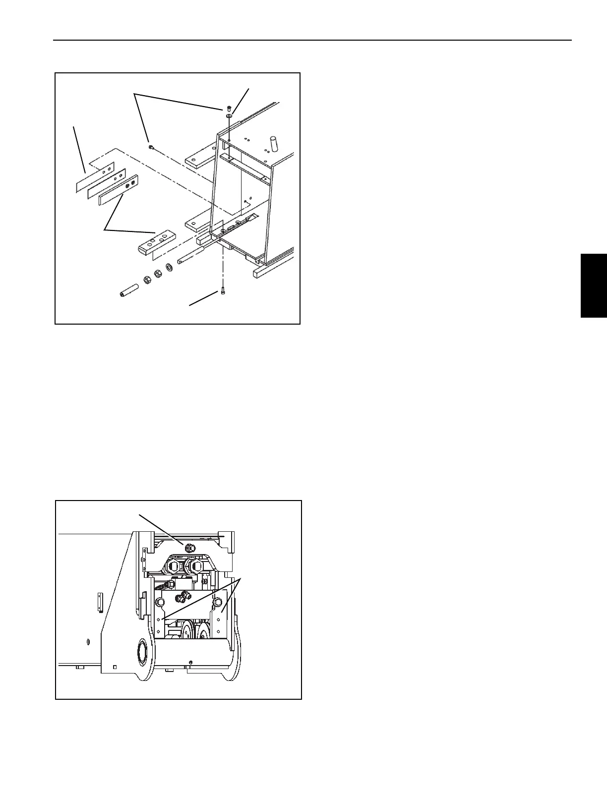
5. Slide the completed 2/3/4 assembly all the way into the
base section.
6. Install the spacers and cap screws through the
telescope cylinder anchor plates.
7. Thread the proportioning cable thorough anchor plate
and install the anchor plate (Figure 4-19) in the following
order:
a. Washer
b. Hex nut
c. Cable protector
CABLE TENSIONING
GENERAL
A boom assembly is considered properly timed when
telescoping sections extend equally relative to each other
and bottom out simultaneously at full retraction and do not
spring back out after retract pressure is returned to neutral.
Hydraulic extend cylinder construction will dictate which
extendable section will be the driver that the other extend
sections will need to be adjusted to utilizing cable
adjustment.
A single stage cylinder will control first extendable section.
A dual stage cylinder will control second extendable section.
Timing sequence of cables will depend on number of
sections and the extend cylinder construction.
Design intent of the cable tensioning is to balance the
preload of extend and retract cables for each extendable
section. In addition, sequencing of the sections during
retraction requires retract cables of every section to be
indexed relative to each other.
Tensioning Setup Procedure
Tensioning must be done with the boom in the horizontal
position.
When tightening/loosening the first (adjustment) nuts on
cables, secure cable using the wrench flats at the front of the
cable ends to prevent cable twist. Excess twisting of cables
can cause premature failure.
Ensure boom is completely assembled and fully retracted.
1. Mark the front of each section with a chalk line as
indicated in Figure 4-20.
2. Extend and retract boom several times to establish
working state of cables.
3. Extend boom so scribed lines are exposed by
approximately 12 inches.
4. Measure the extension gaps between each boom
section and scribed line and note values.
5. Retract boom so that the scribed lines are exposed by
approximately 6 inches.
6. Measure the retraction gaps between each boom
section and scribed line and note values.
7. Extend and retract the boom a few times and then
repeat measuring the extension gaps.
8. Adjust all corresponding cables according to
Cable
Tightening Sequence
instructions.
FIGURE 4-18
Cap Screw
Washer
Shim
(as required)
Wear pads
Cap Screw
FIGURE 4-19
Proportioning
Cable
Extend Cylinder
Anchor Plate

 Loading...


