National Crane 01-22-2019 Control # 051-08 7-3
1300A OUTRIGGERS
4. Tag and remove the hydraulic hoses connected to the
extension cylinder (Figure 7-7).
5. Remove the extension cylinder bolts (Figure 7-7) and
lower the base of the extension cylinder to the bottom of
the outrigger box. See next step for later versions of
outrigger box.
NOTE: Place a piece of wood under the cylinder so that
the cylinder can be lowered to the bottom of the
outrigger box.
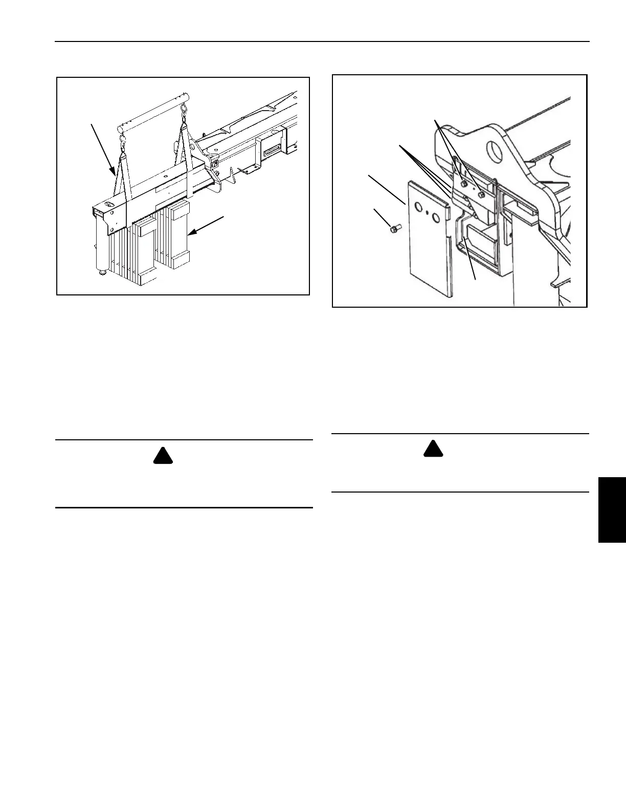
6. Later versions of the outrigger box have a removable
end plate (Figure 7-3) to provide access to the extension
cylinder. Remove the end plate.
7. Cranes equipped with the Outrigger Monitoring System
will have a string potentiometer attached to the inside of
the end plate. Remove string potentiometer using the
procedures under String Potentiometer, page 7-7.
8. Unbolt the cylinder and lower it to the bottom of the
outrigger box.
9. Remove the wear pad set screws in the top of the
outrigger beam and back off the top wear pads (7)
(Figure 7-1). Access is through the access hole in the
end of the outrigger box (5) (Figure 7-1).
10. Remove the wear pad set screws on the side of the
outrigger beam and back off the side wear pads (8).
11. Place blocking material under the outrigger beam
(Figure 7-2).
12. Pull the outrigger beam out of the outrigger box with the
lifting device.
13. Position the outrigger beam on the blocking material.
Inspection
Inspect the outrigger beam for bends, evidence of cracks, or
other damage. Check the outrigger beam internally for
hydraulic fluid, which may indicate a leaking cylinder, loose
connection, or damaged hydraulic line.
Installation
1. Apply grease (EP-MPG) to the bottom of the outrigger
beam.
2. Screw the bottom wear pads on the outrigger box in until
about 0.25 in (6.4 mm) is protruding. This keeps the
beam off of the bottom of the outrigger box.
3. Slide the beam into the outrigger housing.
DANGER
Keep hands out of the access hole when removing the
extension cylinder bolts. The barrel is free to drop when
the bolts are removed and cause personnel injury.
Blocking material
must be capable of
supporting the
outrigger beam.
Use lifting
straps. Do not
use chains.
FIGURE 7-2
DANGER
Blocking material must be able to support the outrigger
beam and not allow the beam to tilt or slide.
FIGURE 7-3
Extension Cylinder
Hydraulic Hoses
Extension
Cylinder Bolts
Nonadjustable
Wear Pad
End Plate
End Plate
Bolt

 Loading...


