SWING NBT30H-2 SERVICE MANUAL
6-6 03-20-2019 Control # 613-06
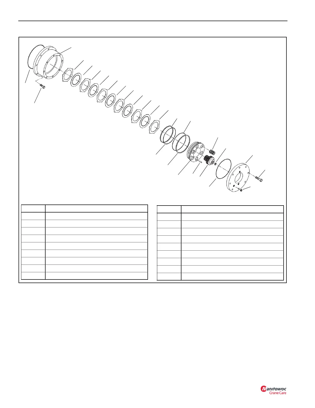
SWING BRAKE
See “Gearbox Disassembly” on page 6-4 for gearbox
removal from the crane. Use the following procedure for
swing drive disassembly.
Disassembly
(See Figure 6-3 for item number identification.)
1. Scribe a mark on the edge of the brake end plate (18)
and the top of the brake housing (1) to aid in reassembly.
NOTE: The brake end plate (18) is spring loaded and
needs to be loosened so that the pressure on the
end plate is distributed evenly.
2. Alternately loosen the eight capscrews (19) one turn at a
time until all internal spring force is relieved.
3. Remove the brake end plate (18) from the brake
housing (1).
4. Inspect the brake end plate O-Ring (13) and replace if
necessary.
5. Remove the brake springs (10) from the assembly.
FIGURE 6-3
Item Component
1 Brake Housing
2Stator Plate
3 Friction Disc
4 Back-up Ring
5O-Ring
6O-Ring
7 Back-up Ring
8 Brake Piston
9Pin
10 Spring
11 Brake Driver
12 Retaining Ring
13 End Plate O-Ring
14 Brake Housing O-Ring
16 Brake Mounting Capscrews (8)
17 Drain Plug
18 Brake End Plate
19 End Plate Capscrews (8)
Item Component
1
2
3
4
5
6
7
8
9
10
11
12
13
18
17
19
2
2
2
2
2
3
3
3
3
14
16

 Loading...


