National Crane 03-20-2019 Control # 613-06 6-7
NBT30H-2 SERVICE MANUAL SWING
6. Connect a port-a-power or other hydraulic pressure
source to the brake release port and slowly apply
pressure until the brake piston (8) clears the brake
housing (1).
NOTE: Note the position of the dowel-pin hole with respect
to the brake release port for reassembly.
7. Inspect the piston O-rings (5, 6) and backup rings (4, 7).
Replace if necessary.
8. Remove the brake driver (11) from the brake
housing (1).
9. Remove the friction discs (3) and the stator plates (2)
from the brake housing.
NOTE: Record the order in which the friction discs are
removed and reinstall in the same order.
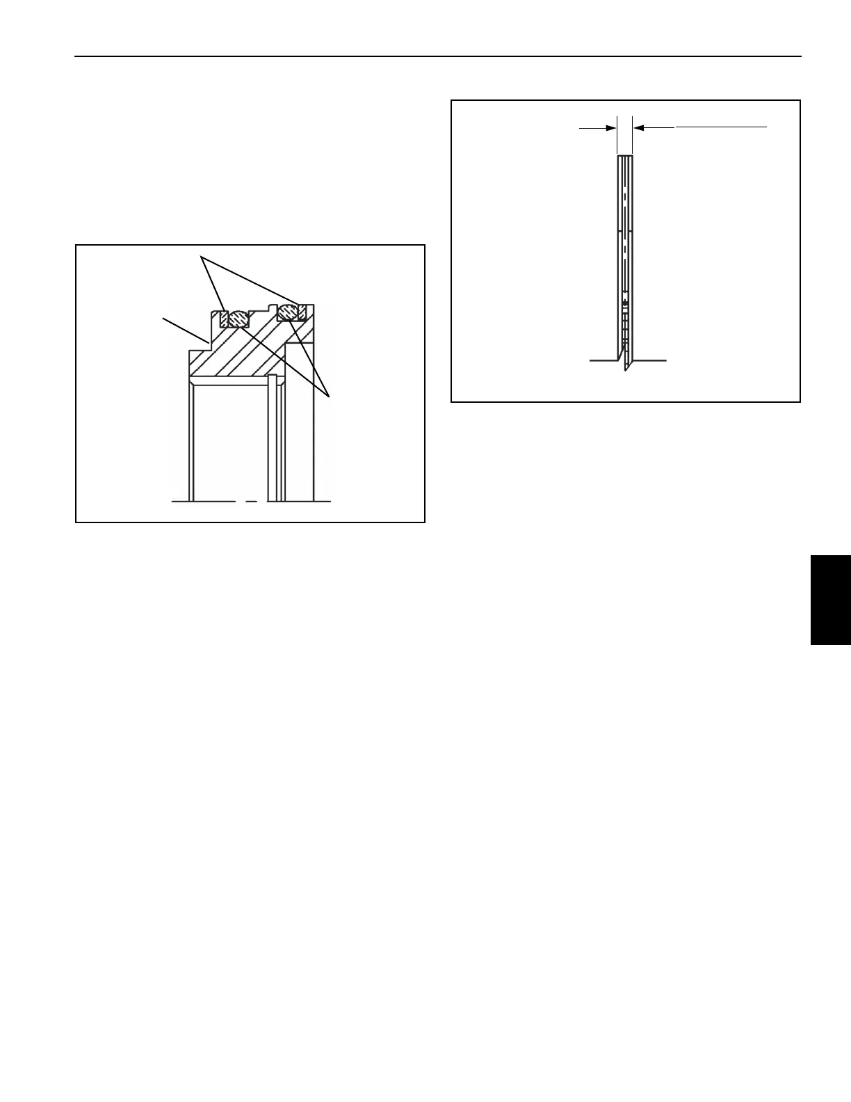
10. Inspect the friction discs for wear and the stator plates
for excessive grooving or burn spots. Check the friction
disc thickness (Figure 6-5).
Assembly
(See Figure 6-3 for reference number identification.)
Assembly of the swing brake is as follows:
1. Install the O-ring (14) in brake housing (1) and bolt the
brake housing to the swing gearbox with the capscrews
(16). Torque the capscrews to recommended values,
refer to Fasteners and Torque Values, page 1-12.
NOTE: Position the brake housing on the gearbox housing
as per removal scribe mark.
2. Start with a stator plate and install the stator plates and
friction discs into the brake housing in the same order
that they were removed.
NOTE: Soak the friction discs in EP-90 oil before
installation.
3. Gently slide the brake piston (8) into the brake housing.
Press down on the brake piston using the heel of both
hands. This will squeeze the o-rings into the case and
set the brake piston against the stator plates.
NOTE: Apply a film of oil to the O-rings and backup rings to
aid in assembly.
4. Install the brake driver (11) into the brake housing. Be
sure that retaining ring (12) is installed in the driver.
5. Install the springs (10) into the holes in the brake
piston (8).
6. Lubricate the O-ring (13) with hydraulic oil and install on
the brake end plate (18).
7. Carefully set the brake end plate (18) on top of the piston
springs (10) so that the springs remain upright on the
brake piston.
FIGURE 6-4
O-rings (5, 6)
Backup Rings (4, 7)
Piston (8)
O-ring
Installation
2 mm (0.080 in)
2.16 mm (0.085 in)
NOTE: Replace if the
thickness is below
1.78 mm (0.070 in.)
New Friction Disc
FIGURE 6-5

 Loading...


