HYDRAULIC SYSTEM NBT30H-2 SERVICE MANUAL
2-14 03-20-2019 Control # 613-06
DIRECTIONAL CONTROL VALVE
Description
The directional control valve (Figure 2-2 and 2-3) is located
at operator control console. To gain access to the directional
control valve, remove the access bolts and remove console
cover.
Control of crane functions is accomplished with manually
operated control levers or optional radio remotes with control
solenoids that are integral to the valve.
The cranes power and the RCL system are activated when
the Stop/Run/Start switch and PTO are engaged. Refer to
operator manual for operating instructions.
Pilot Manifold Valve
The pilot manifold valve (Figure 2-3) is located inside the
operator control console. In A2B and RCL lockout, for swing
stops or If the RCL is being set up, the valve allows operation
in permitted direction only by using system standby pressure
to restrict spool movement. To gain access to the pilot
manifold valve, remove the access bolts and remove
console cover.
Radio Remote Control - (Optional)
If equipped with optional radio remote control, all solenoid
valves on each valve section are energized (Figure 2-2)
when the remote control enable switch is activated. This
closes the solenoid valves.
NOTE: The normal (de-energized) position of the pilot
valves on the valve sections is closed, pilot
pressure is blocked and with the valve’s pilot
control spool chamber, is vented to tank. If crane
power is lost, the pilot control valves are closed and
control of crane functions are disabled.
Energizing a valve coil increases pilot pressure in the
respective valve section pilot chamber. With a solenoid valve
on the valve section energized (open), pilot pressure is
allowed to build for remote operation.
When the radio remote control enable switch is activated, all
solenoid valves on each section act as proportional control
valves.
This allows control of crane functions with the radio remote
transmitter.
NOTE: If an overload condition is sensed, the RCL system
disables the control of boom down, telescope out,
hoist up and swing operation.
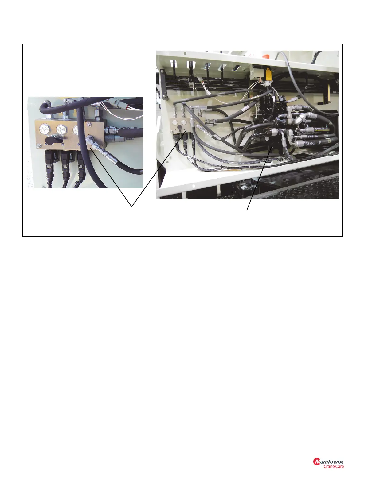
Directional
Control Valve
FIGURE 2-3
8730
Pilot Manifold
Valve
8737

 Loading...


