National Crane 03-20-2019 Control # 613-06 2-23
NBT30H-2 SERVICE MANUAL HYDRAULIC SYSTEM
NOTE: If the RCL is active or in override the pressure
should be in the 2413 kPa (350 psi) range.
NOTE: If the pump does not build up pressure, shut down
the engine and take corrective action.
7. Operate the system under a light load for 5 to 10
minutes.
NOTE: The standby (margin) pressure is the system
pressure with no hydraulic component operating.
8. Check standby pressure and adjust as necessary.
Pump Margin Pressure
The pump margin procedure is as follows:
1. If the machine has never been started or the pump has
been replaced complete See “Pump Startup” on page 2-
22 before going to step 2.
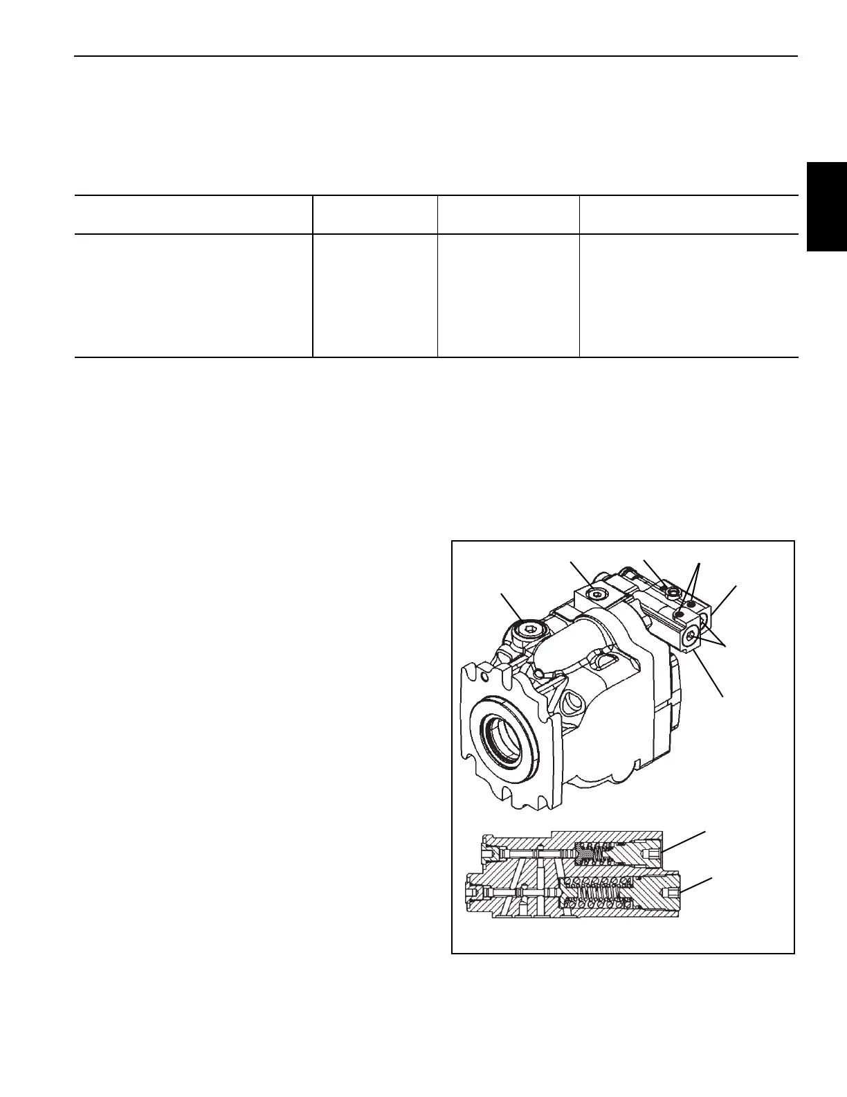
2. Install pressure check gauge at the GP port of the pump
(Figure 2-15).
3. Start engine and idle RPM.
a. Bring up the RCL system and make sure it is not in
lock out mode or enable the RCL override switch.
b. Adjust the Load Sense (LS) adjusting plug
(Figure 2-15) on the pump until the standby
(margin) pressure is at 2482 ± 172 kPa
(360 ± 25 psi) (Figure 2-15).
c. If the pressure needs adjusted loosen the LS set
screw and adjust the LS setting screw “in” to
increase or “out” to decrease to achieve the correct
pressure (Figure 2-15).
d. Tighten the LS set screw.
4. Stop the engine and remove the diagnostic equipment.
5. Check the maximum pump pressure and adjust as
necessary.
Maximum Pump Pressure
1. Install a gauge at the pump pressure gauge port GP on
the pump (Figure 2-15).
2. If the lift cylinder is not installed, plug the extend hose
(larger of two hoses) before proceeding to next step.
3. Start the engine and throttle up to full RPM. Slowly
operate the lift cylinder and extend to maximum
elevation.
4. Hold the boom lift cylinder control lever in the extend
position and check the maximum pump pressure. The
pressure should be 25165.8 ± 517 kPa (3650 ± 75 psi).
5. Adjust the maximum pump pressure with the Pressure
Compensator (PC) adjusting plug (Figure 2-15). While
holding the boom lever in the up position, loosen the PC
set screw then adjust screw in to increase or out to
decrease until correct pressure is achieved, and re-
tighten the set screw.
Valve to be Set
Pressure Setting
MPa (PSI)
Tolerance
kPa (PSI)
Gauge Port and Adjustment
Location
Pump Margin Pressure 2.48-2.82 (360-410) See Range GP Piston Pump (Figure 2-15)
Pump Max Pressure 1.73 (3650) ±517 (±75) GP Piston Pump (Figure 2-15)
Lockout Valve Pressure 7.23 (1050) ±689 (±100)
GLS Piston Pump (Figure 2-15)
Lockout Valve (Figure 2-17)
Telescope Extend Pressure 19.65 (2850) ±689 (±100)
GLS Piston Pump (Figure 2-15)
Tele Relief Valve (Figure 2-16)
FIGURE 2-15
Load Sense
Pressure
Compensator
LS Adjusting
Plug
PC Adjusting
Plug
Set Screw
Adjusting
plug
Gauge Port GP
Case Drain
Gauge Port GLS

 Loading...


